AircraftProfilePrints.com - Museum Quality Custom Airctaft Profile Prints
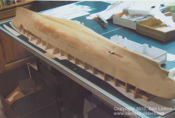
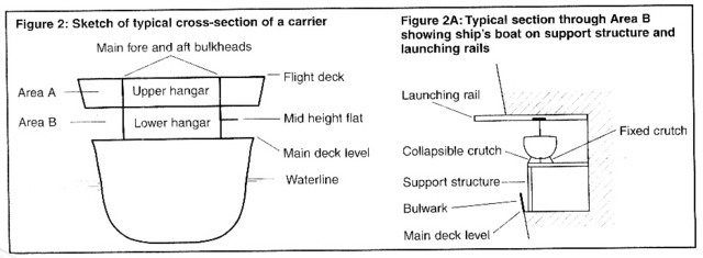
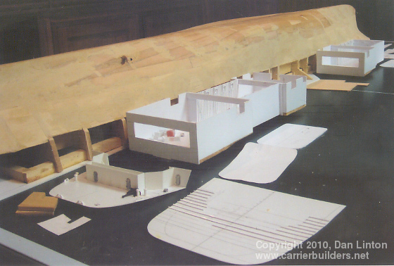
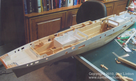
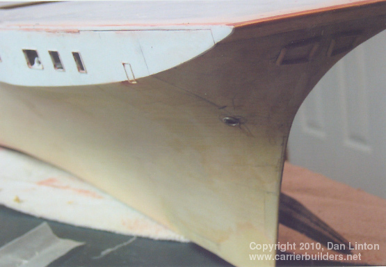
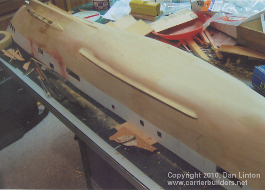
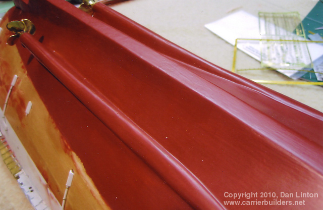
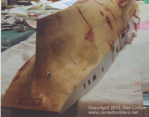
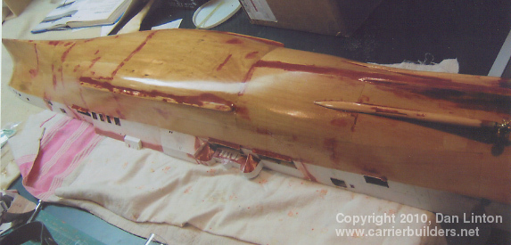
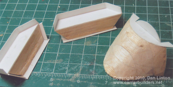
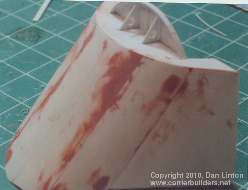
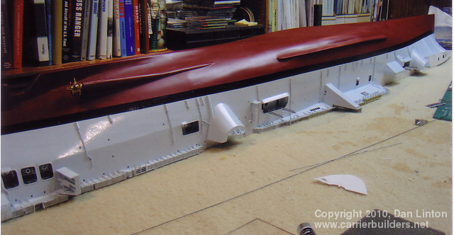
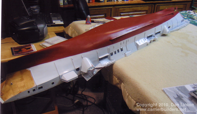
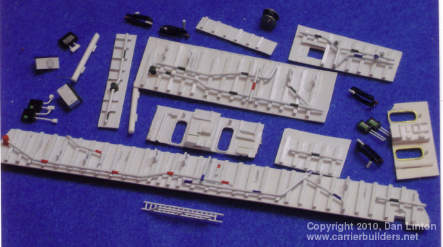
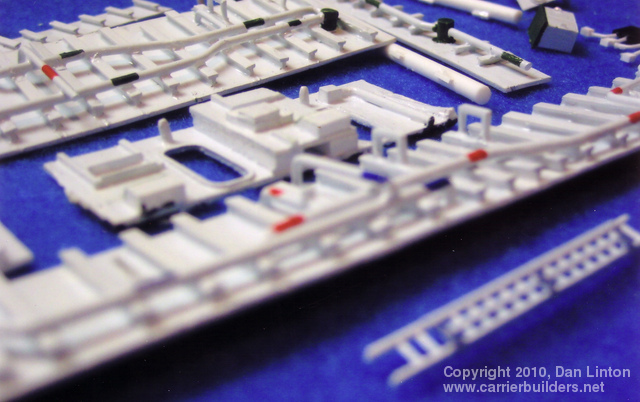
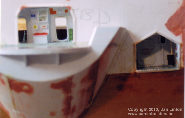
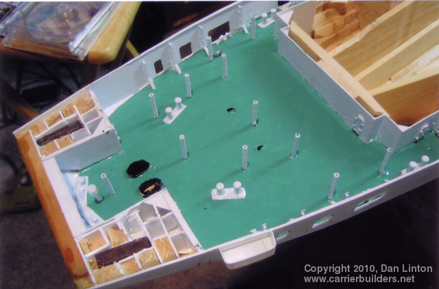
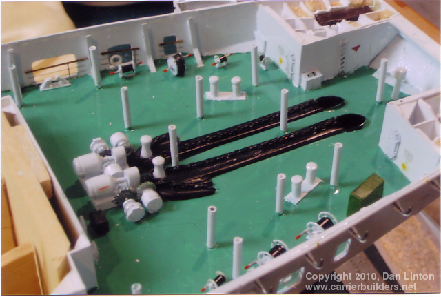
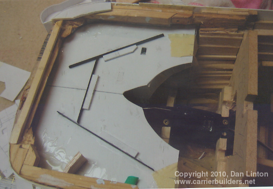
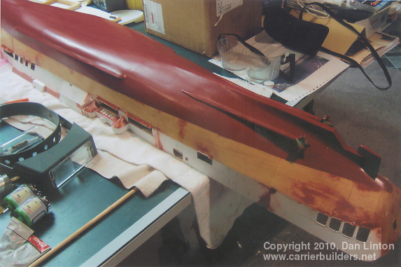
I wonder if there is a modeler in the world, particularly one involved in scratchbuilding, who has gone through an entire build without making a serious mistake? If there is, that is a person to be admired. It certainly isn’t me. I mentioned in Part 1 how I attempted to design the hull to be detachable at the waterline but failed and then decided to make the entire flight deck (1.98m or 58½”) removable. In the main picture above the hull, not separable at the waterline, is seen upside down upon a 60/1000” styrene flight deck. One of the consequences of planning, then abandoning, the idea of separation at the waterline was to make completion of the hull more complicated than it needed to be. This sad result derives from the fact that the Bonaventure was originally a British carrier (ex-HMS Powerful) and followed the same design pattern as all British carriers from the original HMS Argus of 1918 through to all the carriers designed and built up to the cancelled ‘Malta’ class of 1944. As seen in picture 1 below, the hangar deck (or decks) was an armoured box sealed from the rest of the ship. Around the box that was the hangar: its floor was the main deck and it projected outwards from the hangar box to meet the hull leaving room for passageways. There were many ‘cut-outs’ in the hull but none penetrated the hangar bulwarks. So intent were the British on a secure hangar that it was not until the 1950’s that a deck-edge lift was incorporated into modifications made in British carriers. Had I planned from the start to create the entire hangar deck as the single large box that the ship actually had, my construction time would have been shortened considerably. As it was, I ended up with two elevator/hangar ‘boxes’ as seen in picture 2. The outside surfaces of the hangar box should have been the bulwarks visible when looking through the hull cut-outs – but that is not what happened. Picture 3 shows the ‘hangars’ I made. These would later be permanently glued to the underside of the flight deck (for reasons to be described in Part 3). The numerous cut-outs at the main deck level can be seen easily in picture 3. Picture 4 shows the bow area with the flight deck in place and picture 5 shows the bilge keels in place and work proceeding around the propeller shafts. The emergence of the shafts from the hull required quite a bit of sculpting. A brass tube was wrapped in different pieces and thicknesses of basswood, carved, shaped, filled, sanded, then eventually varnished and painted as was the rest of the wooden portion of the hull. The results are seen in pictures 6 and 7. Pictures 8 and 9 demonstrate how slim the hull below the waterline was: the fineness ratio was above 8. Nevertheless, these were not fast vessels. Bonaventure is said to have made 24 knots on her trials but her crew often joked that she was the only ship in the navy whose pennant number (22) was also her maximum speed. Picture 10, the final one in this section, shows the stern of the ship with the rudder in place and the heavy application of filler to attempt to make the hull smooth.
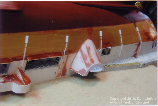
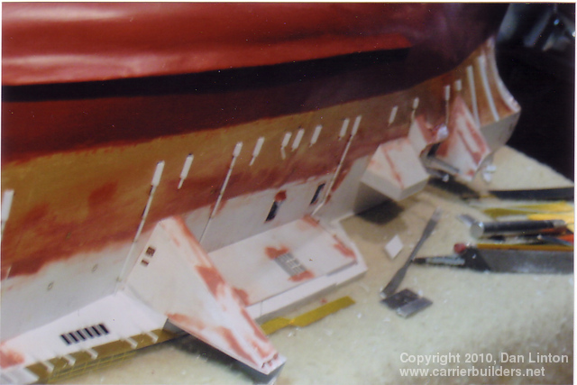
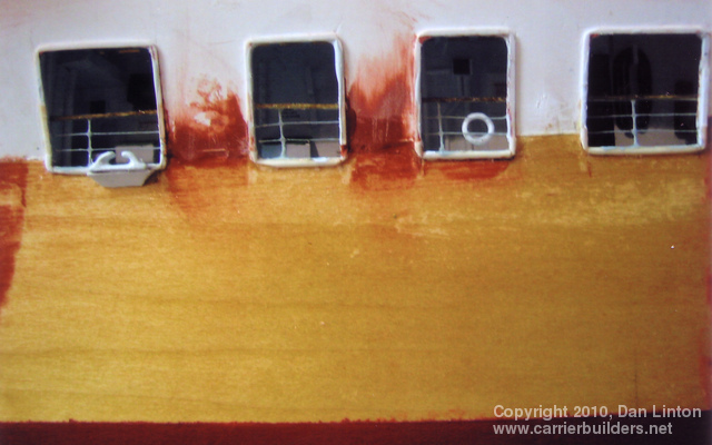
Bonaventure had eight major sponsons. Four supported the four twin 3”50cal. guns and they were quite large and deep; two supported the mirror landing lights; and the final two were general-purpose storage areas. Picture 11, above, shows the two general-purpose sponsons and one of the gun supports. They are shaped balsa wood cores with a sheath of thin styrene (10/1000”) glued on with two-part epoxy resin. This is seen in more detail in pictures 12 and 13 below. Picture 14 shows the port side of the ship with the two gun support sponsons , the mirror array support (narrow triangular structure) and the general purpose sponson forward. Note the large number of openings in the hull. Picture 15 shows the starboard side of the ship but at this stage the support for the starboard mirror array (Bonaventure had two of these systems, one on each side) has not yet been attached. Pictures 14 and 15 also show the numerous drain pipes – over two dozen – found along the side of the hull. These pipes were made from styrene rod (two different thicknesses) and attachment brackets were made by wrapping a spare, thin, length of photo-etch brass around the styrene using needle-nosed pliers (see picture 16). Snips were used to leave a small triangular flange at the end of each bracket – this would then be pushed into a small hole pre-drilled into the hull and secured with CA glue. Then the bottom pipe would be covered by a styrene triangular piece – on the actual ship this protected against constant wave action breaking off the pipe (see picture 17). The triangular pieces were hollow to all fluid drainage at the waterline. Pictures 18 and 19 show line-ups of these pieces before painting, and picture 20 shows that the hull was painted in sections, those sections being defined by the drain pipes. Picture 20 also shows some of the numerous portholes on Bonaventure, a feature all but eliminated on modern carriers.
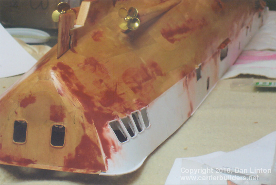
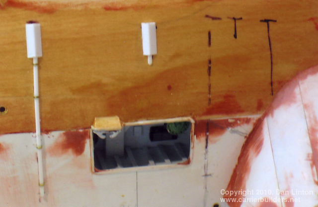
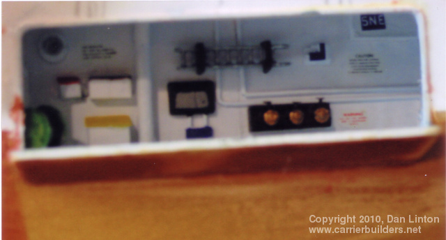
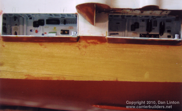
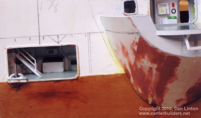
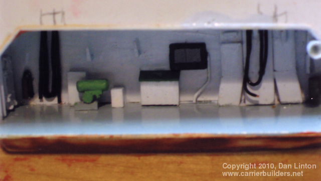
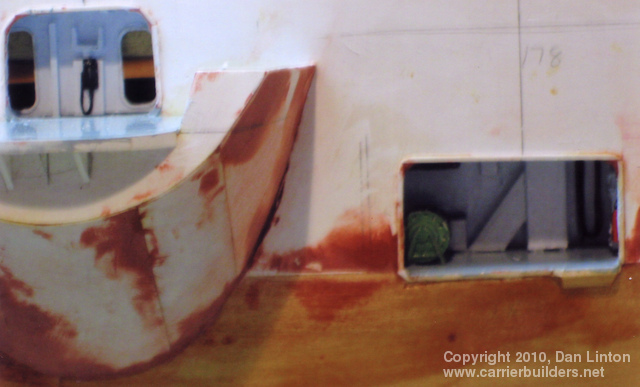
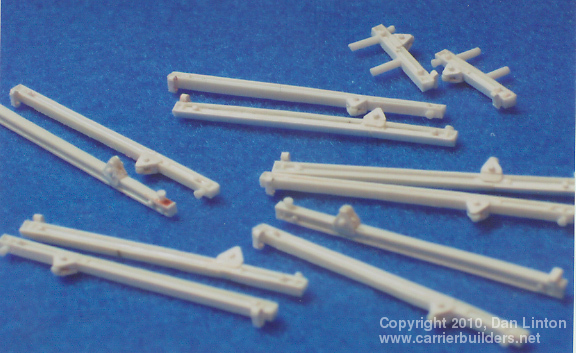
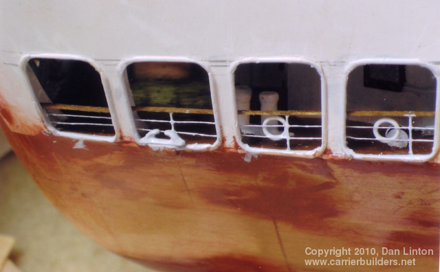
Bonaventure originally had five boats, each having its own storage by a hull opening, with handling gear for lowering to and raising from the sea (note again picture 1 above). Since the carrier spent most of its service life in the North Atlantic (side trips to the Mediterranean and Caribbean were welcome but she was also sent on a cruise to the high Arctic) and had more than its share of storms (no weather recon satellites in the 50’s and early 60’s), these boats were often damaged. Considered as not worth the trouble, four of the boats and their associated gear were removed and the openings were plated over during the major 1966-67 refit. However, I was depicting the ship before that overhaul, so all the boats and the openings had to be included. Picture 21, above, shows one of these openings: missing are the ship’s boat, its cradle, and the overhead pulleys. What is seen is mostly guesswork – I have one picture where the boat is absent but it was grainy black and white and only the left side of the picture, roughly from the thick pipe to the left, has any accuracy. And even then the colours are guesswork. Everything to the right of the pipe is pure conjecture (especially the writing) put there to ‘look good’ and knowing that once the boat is in place, very little of this bulwark can actually be seen. Picture 22, below, shows the two openings for the ship’s boats immediately aft of the superstructure on the starboard side. Again, guesswork and fantasy, especially for the top bulwarks (‘ceiling’). Every single opening require back, side, and top bulwarks (‘walls’). Pictures 23 to 25 show numerous bulwarks: again, all guesswork. Picture 26 shows the opening for crew access aft of the starboard gun support and the opening in the hull leading to the gun deck. Picture 27 is the area on the starboard side directly under the island. Picture 28 shows the opening to the gun deck, starboard side forward, and the small access area used for bringing in supplies towards the bow. Picture 29 is another opening for a boat (midships, port side) which, because of another grainy black and white picture where the boat was absent, is a bit more accurate than the others. Picture 30 is a match for picture 26, only this time it is on the port side aft. Pictures 31 and 32 show the support bars for the wire cables that raise and lower the boats. Picture 33 is a repeat of picture 14: this time look for the pulley supports at the openings for the ship’s boats and notice how far from the hull they extend.
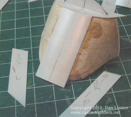
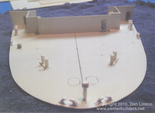
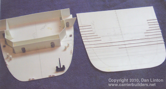
The forecastle comes to us from ships of the late Middle Ages but in the transition from wood to steam this feature no longer really exists. Today, this forward part of the ship at the bow is often called the ‘anchor deck’ or ‘cable deck’ or ‘chain deck’. Nevertheless, the term persisted in the Royal Navy (shortened to the strange looking fo’c’s’le, pronounced “fawk-sill”) and was passed along to the Bonaventure. For the Bonaventure I had good detailed plans of this deck but I did not know what colour it was to be painted. Through the ‘Under the Cat’ website mentioned in Part 1, I sent e-mails to five gentlemen who were crew members of the Bonaventure in the early 1960’s. I received three replies. Vernal Smith and Ron Serink indicated that this deck was painted non-skid green, essentially the same as the green used on the flight deck. Charles Waring stated that the deck was painted dark grey with black anti-skid strips. Picture 34 (above) shows the beginning of the construction of this deck. Picture 35 shows this deck fitted inside the hull. It was at this point that I needed to decide upon the colour and, being so advised by two of three respondents, I went with green (see picture 36). Picture 37 shows the deck almost completed: the gloss paint needs to be dulled to flat. Interestingly enough, when the flight deck is placed over the fo’c’s’le, it looks very much like…….dark grey. All the respondents agreed that the quarterdeck was planked and stained similarly to the teak that formed the topmost rail of the handrails. Unfortunately my plans did not show this planking (perhaps removed in the 1966-67 refit) and so what I produced was meant to be a steel deck (see picture 38). Picture 39 shows the quarterdeck in place: it was already in place when I received the e-mails that it had been planked. Too late! I wasn’t going to rip it out and start again, so…..picture 40 shows a quick brown paint coat and picture 41 show the top bulwark (‘ceiling’) in place. Given the fact that the stern and aft openings in the hull admit very little light (picture 42), the lack of planking here is not a total disaster. Next: Part 3 – the Flight Deck, Elevators, and Hangar
Photos and text © 2010 by Dan Linton December 6, 2010 |