AircraftProfilePrints.com - Museum Quality Custom Airctaft Profile Prints
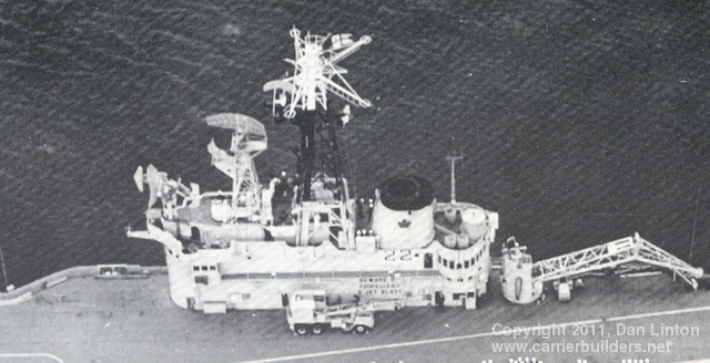
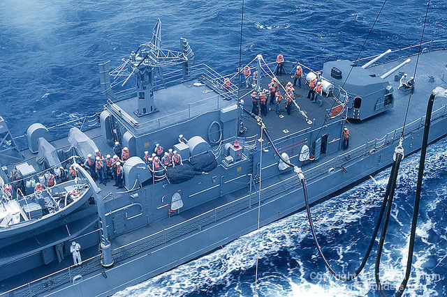
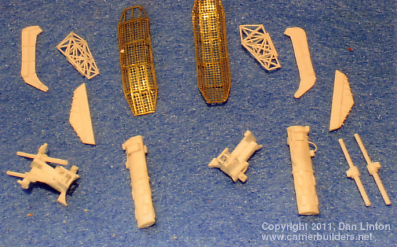
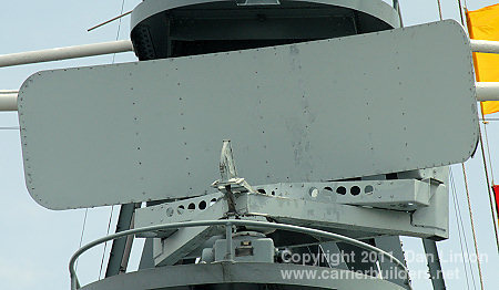
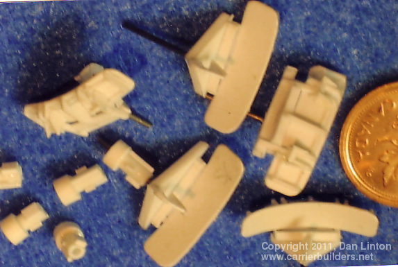
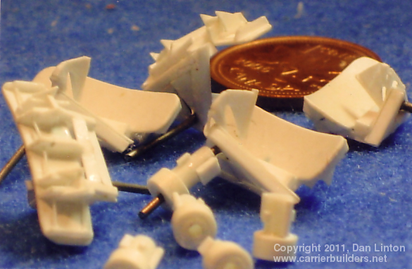
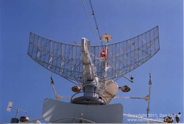
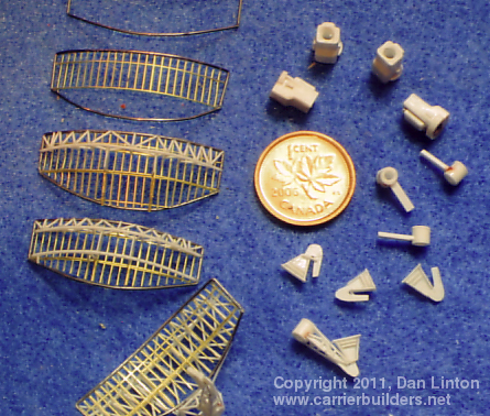
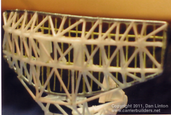
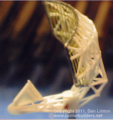
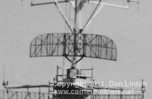
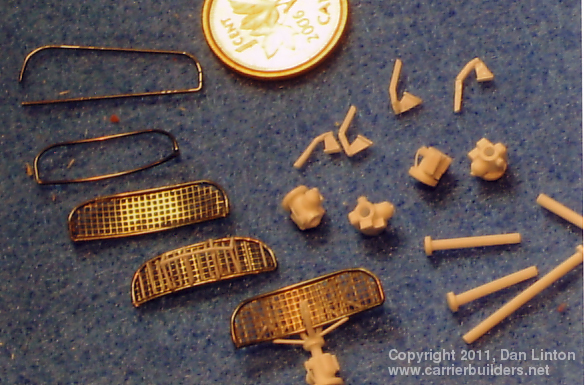
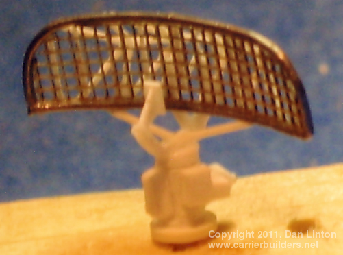
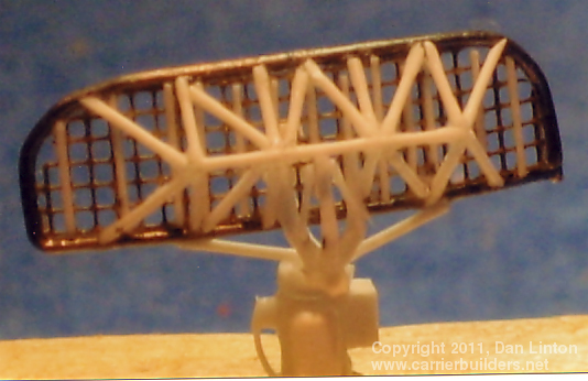
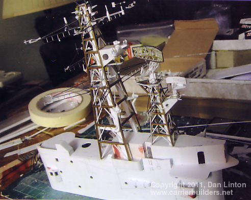
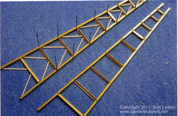
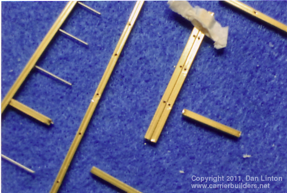
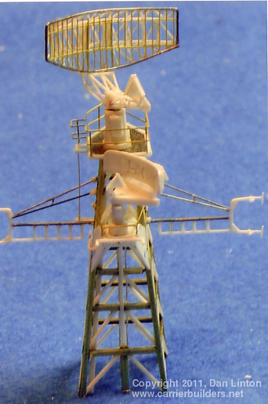
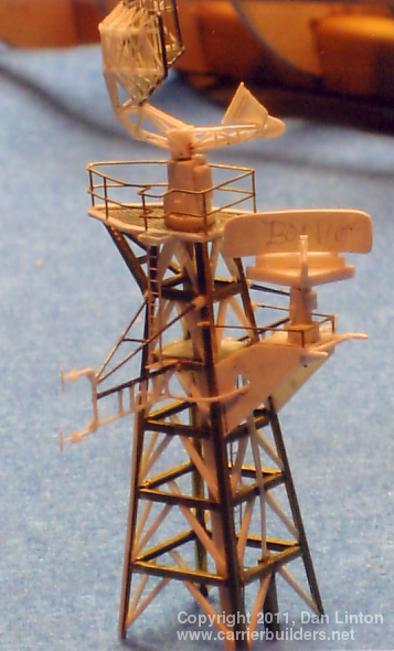
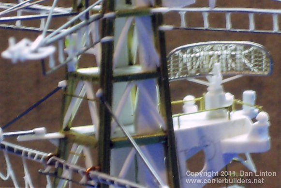
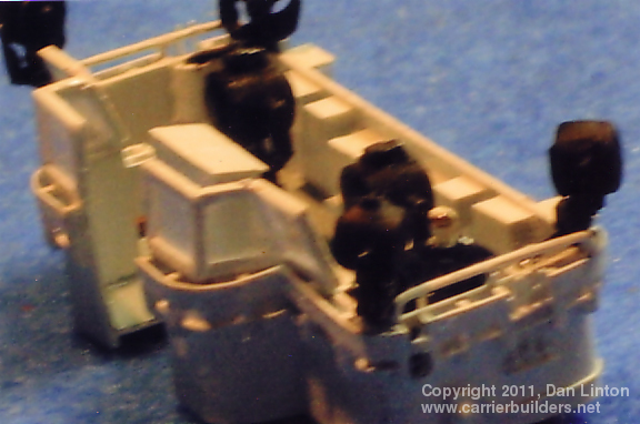
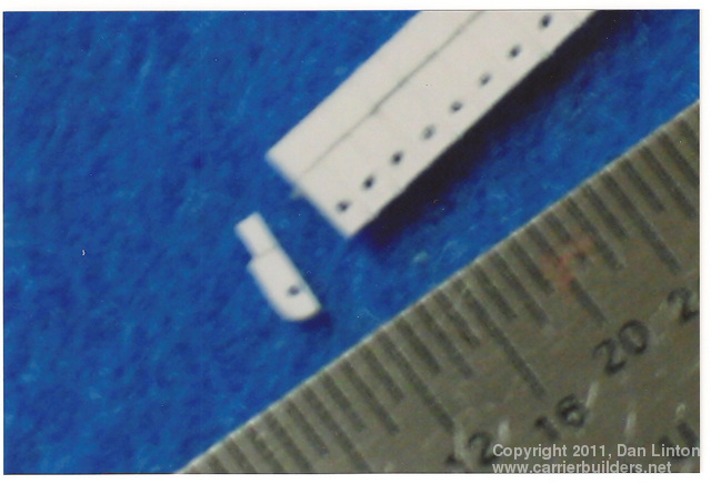
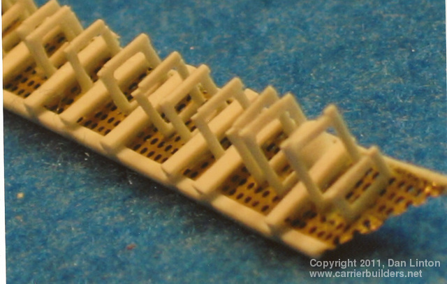
HMCS Bonaventure, from her commissioning in 1957 to her mid-life refit in 1966, had four major radar systems. Looking at the picture above, the first radar on the superstructure (beginning from the left) is the SPS-8A height-finding radar. Certainly, this is one ugly, complex piece of machinery. Picture 1 shows this radar mounted on an American DDR. My attempt at duplicating this radar is seen in picture 2. Note that I produced two sets – the other set is for a future project. Picture 3 shows the completed SPS-8A on the Bonaventure’s island. Going back to the main picture above, the foremast to the right of the SPS-8A carried two radar sets. The lower and smaller radar is a Sperry Mk.2, described as a high-definition surface warning radar. Picture 4 shows the actual radar and pictures 5 and 6 shows my efforts at producing this radar, a task made simpler as the dish is solid and not mesh. And again, I am producing multiple radars here for other projects. At the top of the foremast was the largest radar on Bonaventure, the SPS-12 medium surveillance air search radar. An actual example is seen in picture 7. Picture 8 shows an assembly line that will produce five of these radars. Starting at the top left a wire is bent into shape; then photo-etch from a set that was originally depicting a wrought-iron fence was trimmed and set into place. A second piece of photo-etch was also trimmed and glued into place, and then a large number of 15/1000 styrene pieces were cut and glued. Pictures 9, 10, and 11 show the complexity of a complete SPS-12.
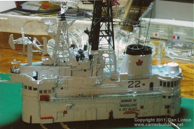
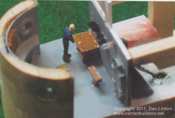
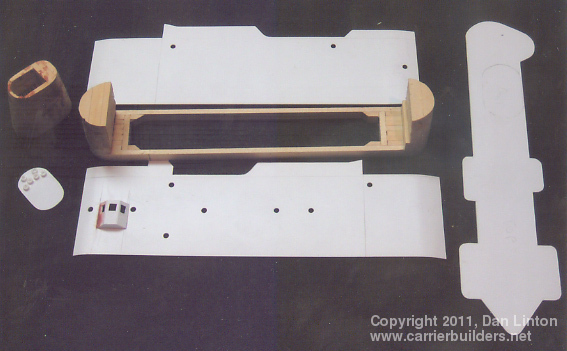
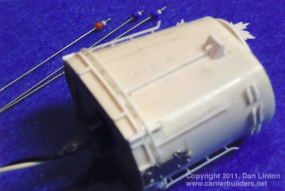
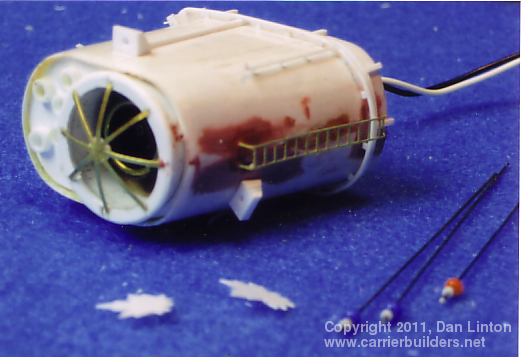
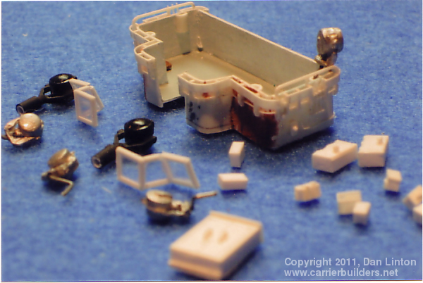
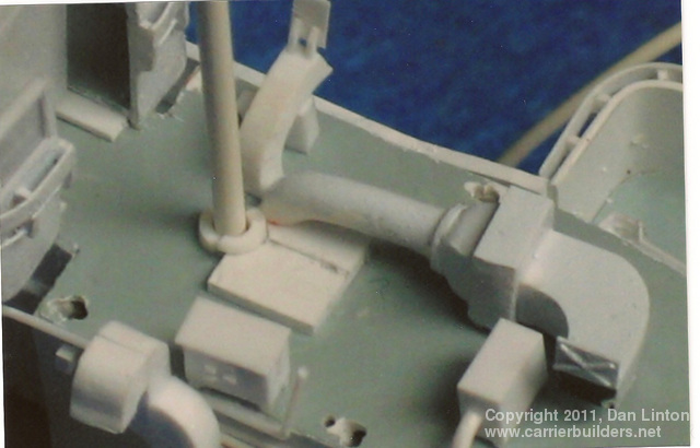
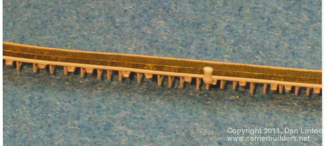
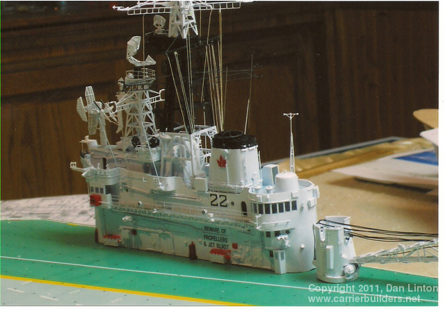
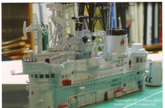
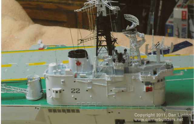
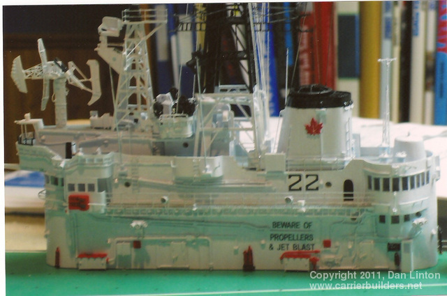
The final radar, and the only one originally carried on the Bonaventure’s main mast, was the SPS-10, seen below in picture 12. This was a surface-search radar. Pictures 13, 14, and 15 show my assembly line for five of these radars. Again, wire, photo-etch, and 15/1000 styrene rod were used, although as can be seen in picture 15 the 15/1000 still appears to be too thick. Interestingly, 10/1000 was far too thin and weak and could not be effectively used here. The radars were built long after I had begun the superstructure or island. Since the island would have to enclose modified servo motors to operate the radars, it had to be stronger and stiffer than simple styrene, thus the wood base seen in picture 16. Notice that the superstructure is a half-circle at either end. The sides of the superstructure, made of 30/1000 styrene sheet, can be seen as bending slightly fore and aft but I would have no end of trouble later trying to have these pieces conform and stay glued to the curve of the wood frame. Note also that the funnel is wood – it would later be sheathed in 10/1000 styrene which is very forgiving and easy to bend. Picture 17 shows the built-up wood structure of the island, with the starboard side attached as well as the roof: the bridge and pri-fly areas have their interiors complete or almost complete. Notice the wires – tiny grain of rice bulbs were used to light up the interior. Picture 18 shows the starboard side glued on (two-part epoxy resin was used as one was gluing styrene to wood) but notice at the left of the picture that the styrene does not follow the curve of the top deck. Finally, the hole in the top deck is for the smoke-generator that will be glued into the smokestack. Picture 19 shows how the island remained for a long time – in order to install the motors for the radars I needed this sided open so I could see what I was doing (not that it helped much, as will be described later). Pictures 20, 21, and 22 show the completed smokestack. Three large antennas are seen in picture 20 – these would be among the last pieces glued on as they are long and sharp and would get in the way as I worked in and around the superstructure. In picture 21, if you look down into the smokestack you can just make out the lip of the smoke generator. Liquid is put into here and then an electrical current boils away the liquid creating smoke. These generators come by way of train modelers: this one in particular, requiring a six-volt charge, is the most suitable for ship models. In the final picture, number 22, the two maple leaves, 10/1000 styrene, will be painted red and then the appropriate decal from the CanMilAir set will be applied. The completed smokestack was glued on quite late in the process, but ahead of the masts.
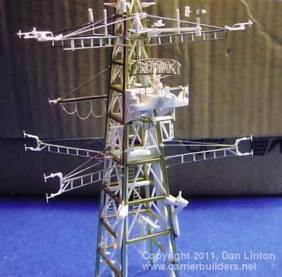
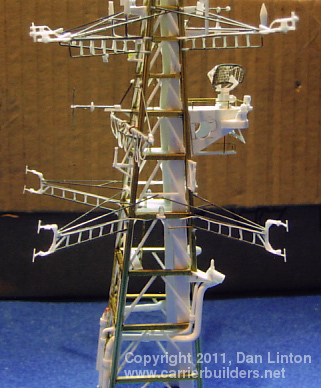
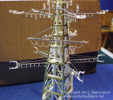
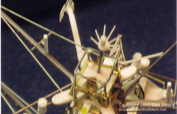
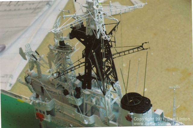
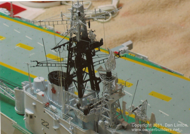
Battleship fans know that the ‘pagoda’ structures found on Japanese battleships are among the most complex challenges to ship modelers. I believe that the masts of the Bonaventure are no less challenging, particularly when the plans I had were for the ship after its 1966 refit. And of course, I began with errors. Picture 24 below, shows the main structures of the foremast and mainmast but the foremast (to the right of the picture) is wrong – it is the foremast after 1966 and it had to be completely undone. The main legs of the mainmast are hollow brass pieces, as is the lowest of the cross-pieces. The other cross-pieces are L-shaped pieces of brass glued to wires that join the legs. The white styrene braces are L-shaped with the bottom five pairs being 3/64” and the top five are 1/32”. These are seen in picture 25. Picture 26 shows the drill points in the legs (materials for the foremast to the right were all abandoned and the hollow square pieces of brass were replaced by L-shaped pieces). Pictures 27 and 28 show the complete foremast with the Sperry Mk.2 (lower) and SPS-12 (upper) radars in place. Pictures 29, 30, and 31 show the mainmast, holding the SPS-10 radar and all manner of other instruments. What appears to be drooping wire in picture 31 is 10/1000 styrene, bent and glued into shape. Picture 32 shows how crowded this structure is. This is reinforced by picture 33 below showing the top of the mainmast. Before they could be attached to the superstructure, these masts were painted (picture 34).
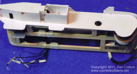
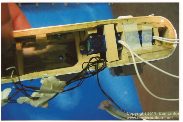
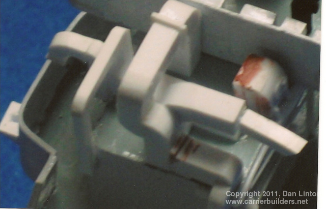
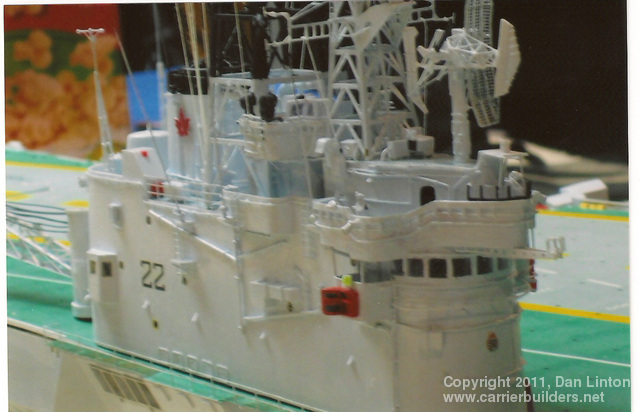
Pictures 35 and 36 show two servos installed in the front of the island to activate the SPS-8 and SPS-12 radars and the numerous wires (black) that attach to grain of rice bulbs that will light up the front and rear of the island. The servos had to be torn out and re-sited and still the SPS-8 would only turn in a very jerky motion. Because the SPS-8 is located so far forward, I could not get a servo directly under it and used a gear on the servo to turn a brass tube that had a gear attached to it – but often the gear teeth miss each other. The SPS-12, on the other hand, turns smoothly. At this point, the smokestack has not been added so its wires are not to be seen. Once the servos were in, the port side of the island was closed in with 30/1000 styrene. But bending this thickness around the front and rear ends of the island was almost impossible: eventually I used 20/1000 pieces at these ends. Once this was done, the first major sub-structure to be added to the island was the searchlight platform, seen partially built in picture 37 and completed in picture 38. Its location on the island is seen in picture 39: this picture also shows many of the details of the starboard side of the island. Picture 40 shows some of the vents and other structures found on the roof of the superstructure: note the four holes – here the legs of the foremast will be inserted. Picture 41 again is the roof of the superstructure but these vents are found inside the legs of the mainmast – I didn’t have clear pictures of this area so some of what you see is guesswork. Picture 42 shows the front of the island: masking tape covers the windows of the bridge. Detailing has begun here, making use of various thicknesses of styrene rod. Both around the bridge and searchlight platforms, at the top outside edge, are wind baffles. To make these involved cutting dozens of supports with a hole drilled in for the placement of .015 styrene rod (picture 43). These are seen in place in picture 44. Was this tiresome and tedious? In a word – yes ! Almost as tedious was creating the long walkway that goes along the port side of the island. Picture 45 shows the underside of the walkway: picture 46 shows a topside view. All the support structures were necessary because four sets of pipes ran underneath this walkway. The island was now ready for final detailing – here, like elsewhere, HMCS Bonaventure was a pipefitter’s dream, but likely a maintenance nightmare.
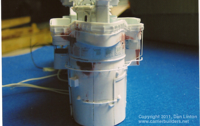
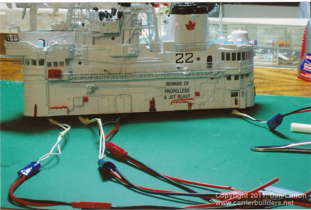
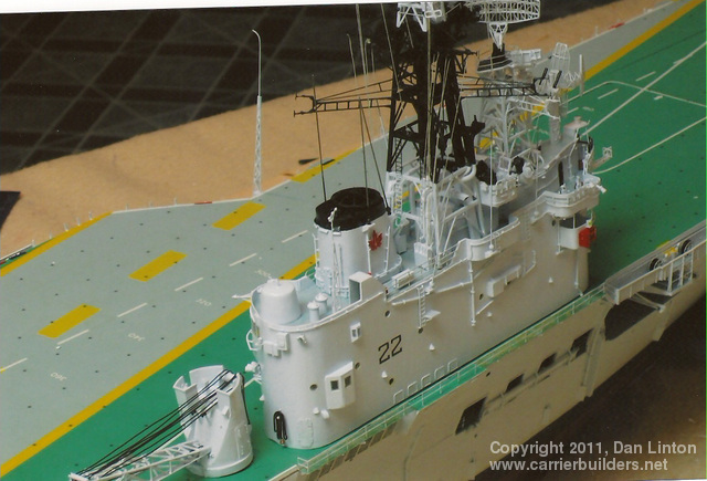
When the island was test-fitted to the flight deck, my suspicions were confirmed – I had far too many wires to stuff into the space available. Notice in picture 47 (above) how long the wires are from, for example, the servos (white wires to the left) to the red plastic connectors. These wires could not be stuffed inside the island and were simply too long to fit efficiently into the hull. They would have to be shortened and that was done, but it was delicate work as everything by this time was on the island (picture 48). Just before the island was put in place, the ship’s crane was installed. Picture 49 shows the beginning of construction – brass and plastic and the housing at the right is made of layers of balsa wood, cut and sanded, then sheathed in 10/1000 styrene. Picture 50 shows the almost completed crane: the small structure seen at the right will be attached to the flight deck – the crane arm rests on this structure. Picture 51 shows the crane, with pulley wires in place, on the flight deck behind the superstructure. The superstructure is complete at this point except for windshield wipers on some of the windows. These will come from an N-scale stainless steel photo-etch fret designed for model railroaders (not yet delivered at the time the pictures were made). The rigging turned out reasonably well. Picture 52 shows the complexity of the mainmast and again, one can look into the smokestack and see the lip of the smoke-generator. Picture 53, while not the most sharply-defined, nevertheless is useful: the ship’s crest (a decal from CanMilAir) can be seen at the front of the island. Pictures 54 and 55 show the starboard side of the superstructure. Picture 56 is a fairly clear study of the roof of the superstructure and the masts: notice the large number of whip antennas in this view. They were the last pieces to be attached. Picture 57 shows the starboard side of the island from the rear quadrant. Altogether, the island and crane took more than six months to complete. Removing the island from the flight deck, then putting it back, is a frightening task: some of the pieces, particularly on the masts, are so delicate that a good sneeze could blow them away and just touching the ends of the arms that stick out from the masts will guarantee tiny broken pieces and more gluing. And that happened several times during construction. But its time to move on. Next: Part 5: All the Other Details
Photos and text © 2011 by Dan Linton August 9, 2011 |