AircraftProfilePrints.com - Museum Quality Custom Airctaft Profile Prints
Once the basic structures are complete, then putting on the details is what makes modeling so satisfying – or nerve-racking! I never fail to be impressed by modelers whose 1:700 models look so realistic, or whose scratch-built aircraft sit on the top of a tin of Humbrol paint looking for all the world like a 1:72 effort. At some point (1:350? 1:200?) it becomes possible, even necessary to model everything the eye can see. This is certainly the case in 1:144 and I do envy the 1:96/1:100 modelers who can purchase a multitude of fittings and save hours of labour. As for 1:72 builders, on the one hand detailing is easier (eight time the size by volume of a 1:144 scale model) but less forgiving – each piece is easier to see and any flaws are more difficult to hide. And as for 1:48 and 1:32 models – at those scales one can create crew members with dirty or clean finger nails.
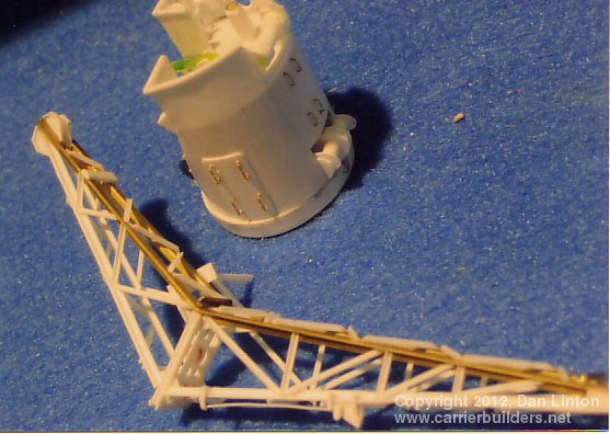
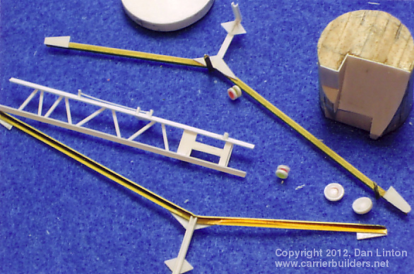
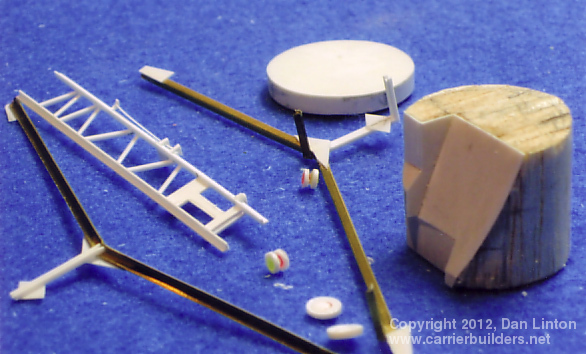
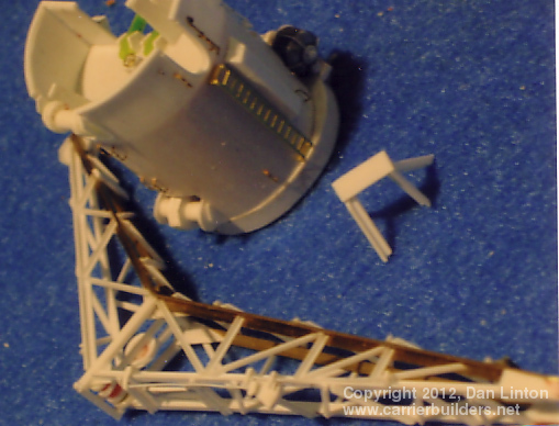
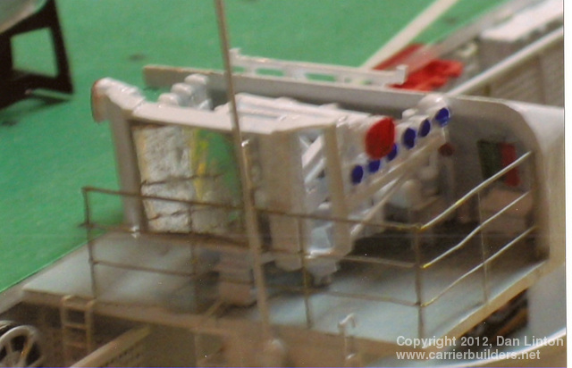
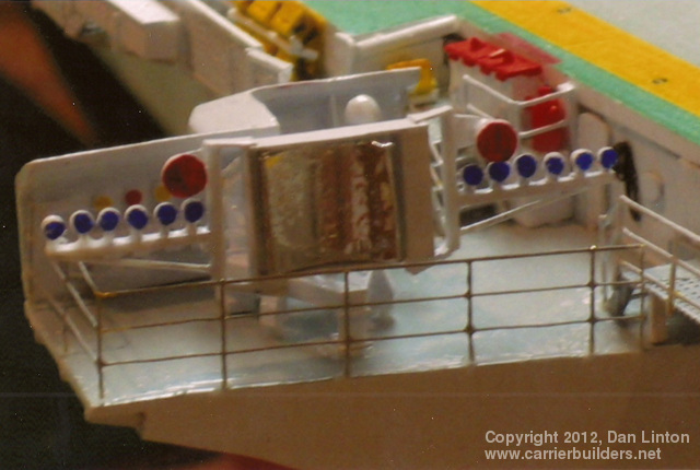
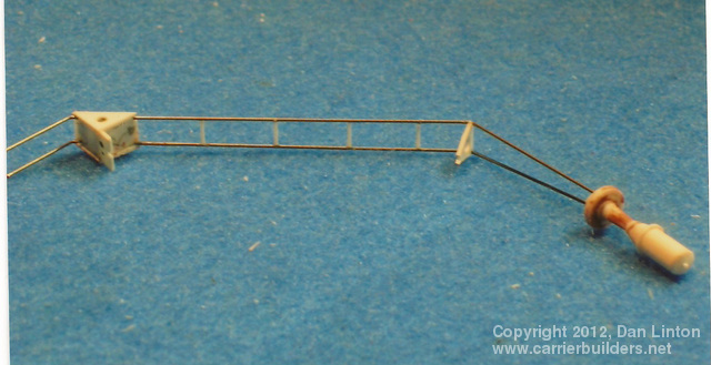
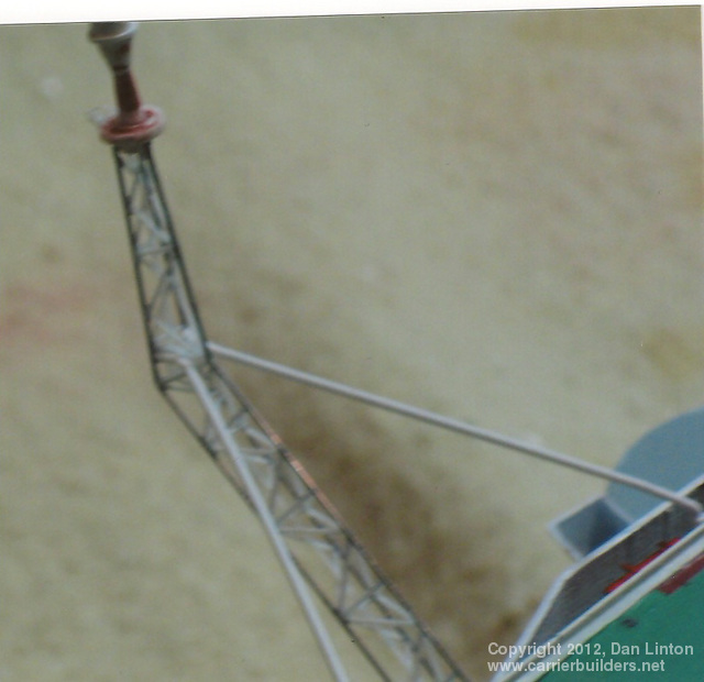
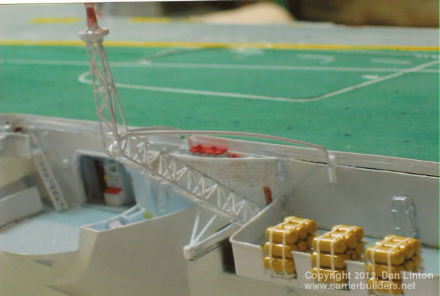
On Bonaventure, the large crane aft of the superstructure had two major functions. At dockside, loading the ship with stores, aircraft, and other heavy items (a load of trucks was once brought to Norway for an exercise involving the Canadian army) which required heavy lifting. At sea, this crane was used to hold up the large fuel hoses when Bonaventure, using underway replenishment, refuelled her escorts or took on fuel or other products from supply ships. Picture 1 (above) shows the major structural parts for the ship’s crane. Note that balsa wood, sheathed in 10/1000 styrene, has been used for the core of the crane support, and a mixture of bras and styrene has been used for the crane arm. Picture 2 shows these pieces from a different angle. Pictures 3 and 4 shows the crane almost completed: the strange looking piece to the right is a bar that supports the crane in its resting position. It will be glued directly to the flight deck. Picture 5 shows the completed crane in its position aft of the superstructure.
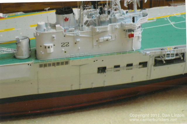
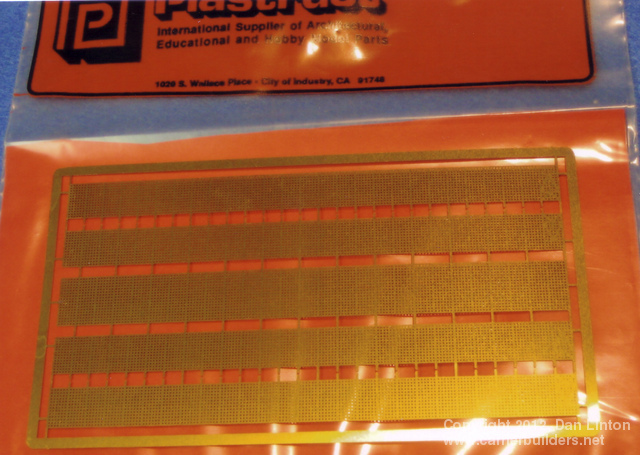
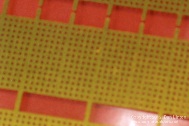
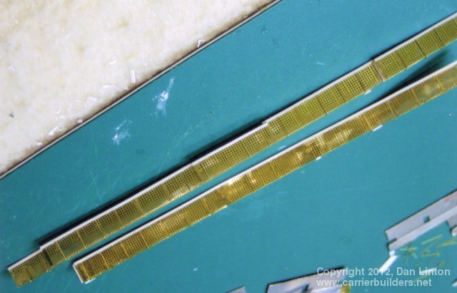
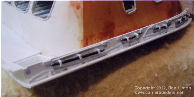
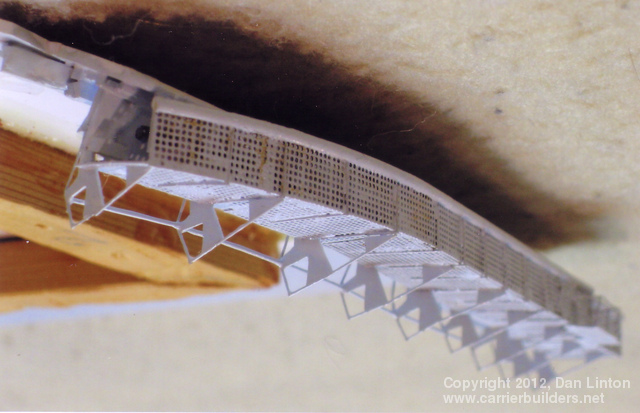
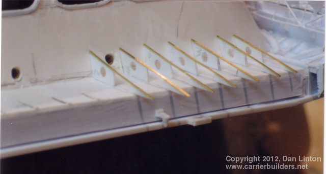
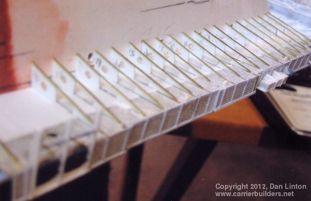
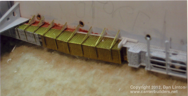
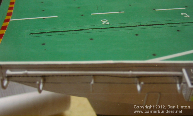
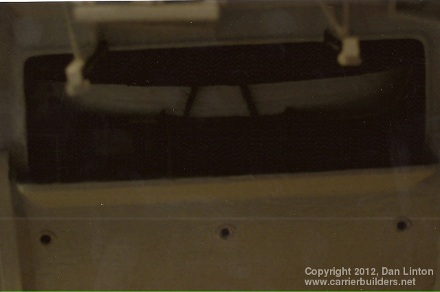
Catwalks (and I don`t know if this term originated with the British or the Americans) have been a feature of every aircraft carrier since the original HMS Argus of 1918. Usually found only on the port and starboard sides of the flight deck, in a few cases – and Bonaventure is one of them – there is a ‘gallery’ or catwalk across the stern of the flight deck. The need to shed water means that catwalks are not solid structures – some pattern of perforations penetrates the ‘floor’ although the sidewalls might be solid. In the case of Bonaventure, the pattern was regularly spaced circular holes on the floor and, no doubt to save weight, on the sidewalls as well. On the model, these were represented by a photo-etch fret, as in picture 6 above (repeated below as picture 7) and picture 8 below. The sidewalls and floors were re-inforced on Bonaventure by welded steel beams – represented here by another photo-etch fret (picture 9). Dozens of these had to be cut out and then glued on using super-glue. Picture 10 shows two catwalks: the white styrene represents the top or handrail portion. This was done using 1/32” ‘L’ shaped styrene superglued to the photo-etch. Picture 11 shows the stern of the flight deck, upside down, just prior to having the ‘gallery’ or catwalk glued on. It is glued on in picture 12, again upside down. Picture 13 shows the completed stern catwalk. It was easier to work these catwalks upside down, particularly when the underhanging support structures were so delicate and complex, as seen in pictures 14 through to 17 below. Picture 18 actually heads the next chapter – it shows a typical catwalk section.
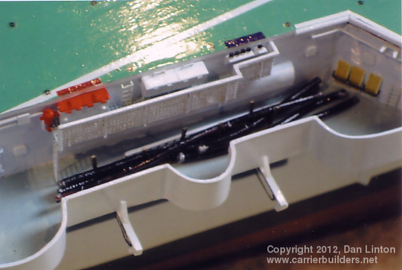
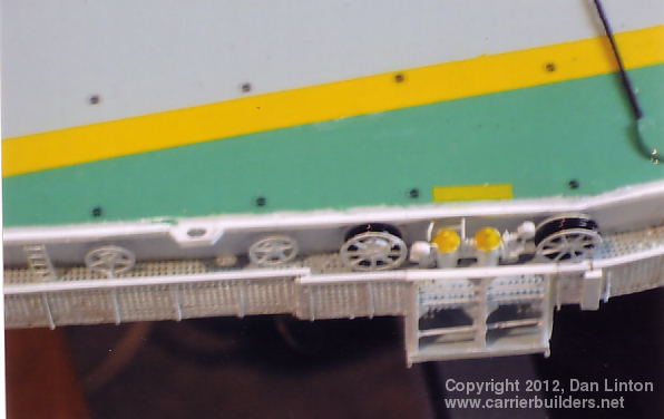
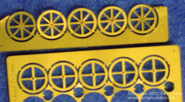
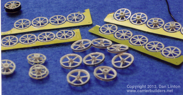
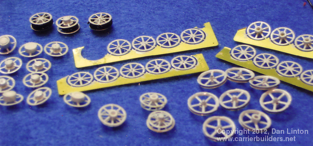
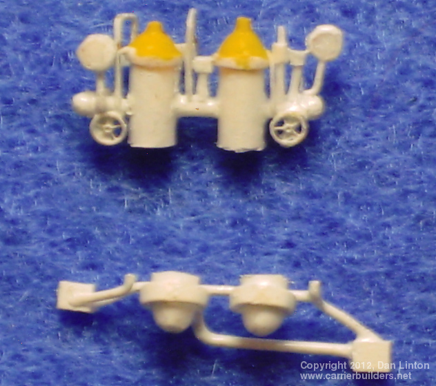
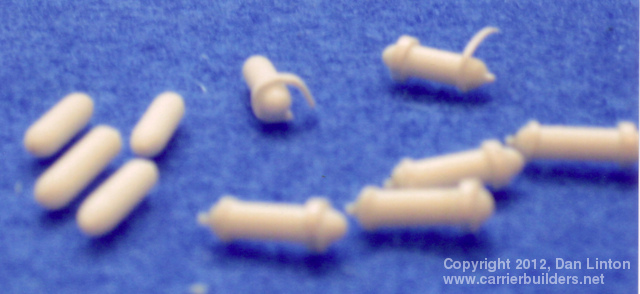
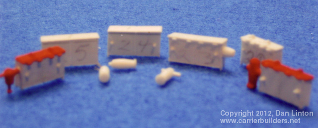
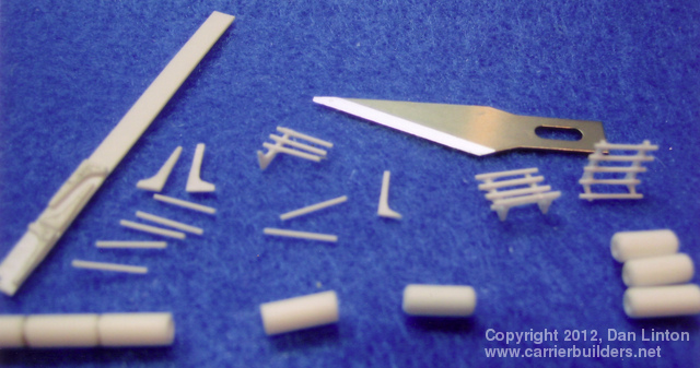
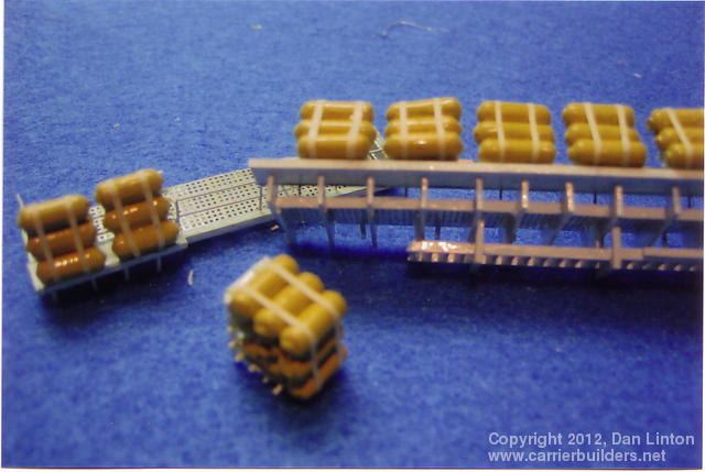
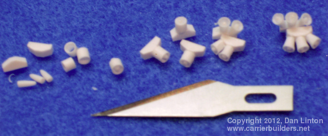
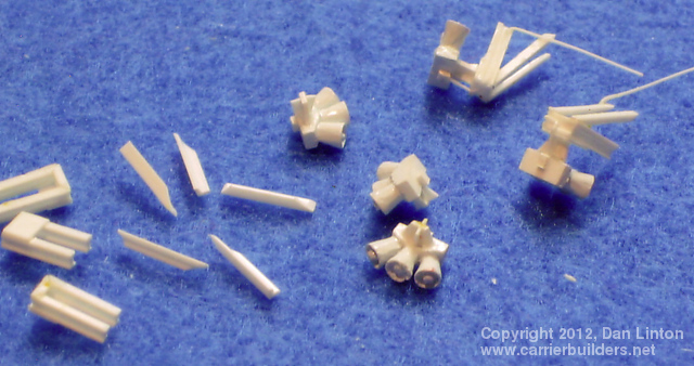
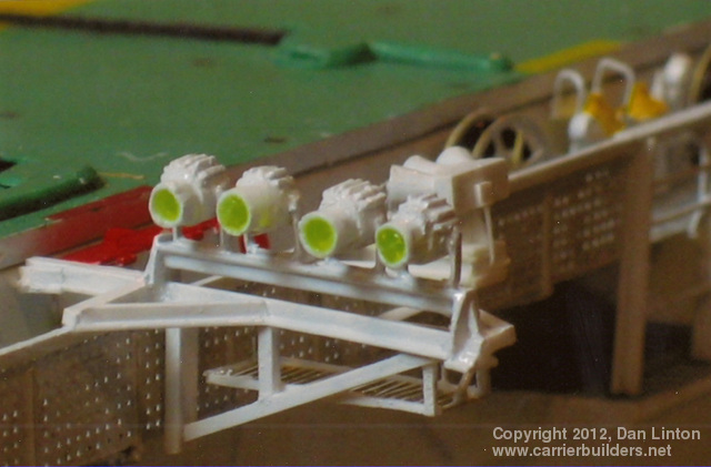
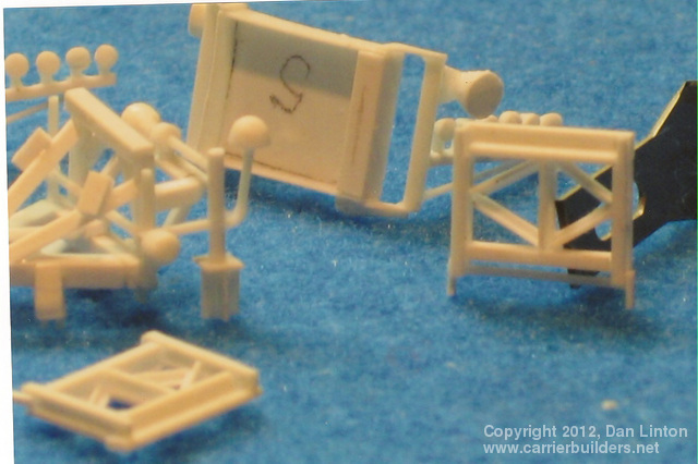
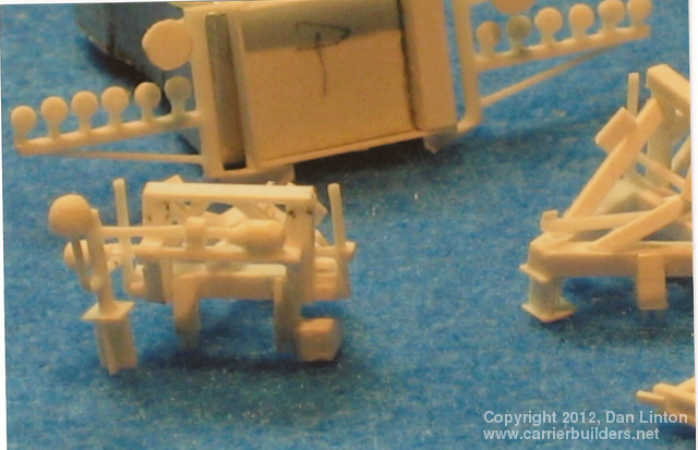
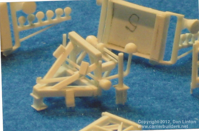
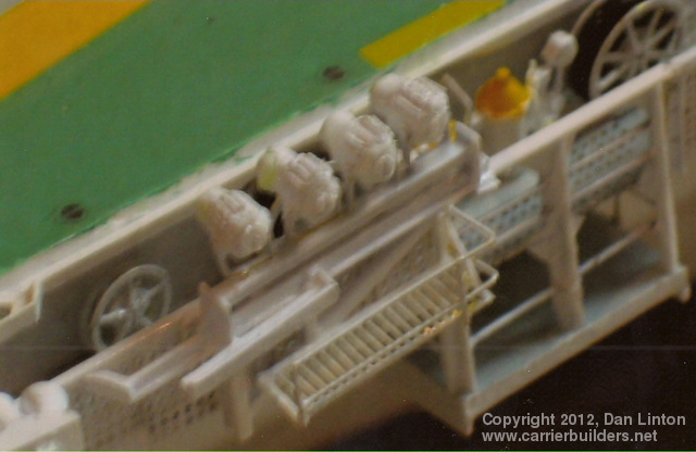
Bonaventure had literally hundreds of hoses and dozens of hose reels. In picture 18 above, four of these reels can be seen, two with hoses on them (black wire was used) and two bare. These reels came from photo-etch frets, usually of an assortment of hand-brakes, used by railway modelers. In picture 19 below the handbrakes with four spokes on the bottom row will be modified to produce reels with eight spokes, as seen along the top row. Each reel required two handbrakes; sometimes the rear one had eight spokes and the one in front was smaller with only five spokes, as seen in picture 20. Picture 21 simply reinforces how many of these had to be made. The picture at the head of this paragraph shows a pair of yellow-topped structures with two large hose reels to each side. These were condensers, in pairs, and four pairs were found on Bonaventure, one pair in each quadrant. Picture 22 shows a pair: once finally assembled cuts had to be made as part of the structure was below the level of the catwalk. These condensers began as lengths of styrene road, cut and shaped, and then other pieces were added (picture 23). Picture 24 shows some ‘fireboxes’. Inside these boxes with red-painted lids were fire hoses, connected in times of emergency to the pumps, here painted in red, associated with each box. There were almost two dozen of these on Bonaventure found in the catwalks, and two were beside the island facing the flight deck. Picture 25 shows the beginning stages in creating the life raft `bags` and their support structures. Platforms for some of these life rafts are seen in picture 26 and in picture 27 some have the `bags` attached. Notice in the foreground of this picture a grouping of nine bags. Three of these groupings (thus 27 `bags`) were located on the foreward large sponson on the starboard side (picture 28). Other locations were port side aft (picture 29) and starboard side aft (picture 30).
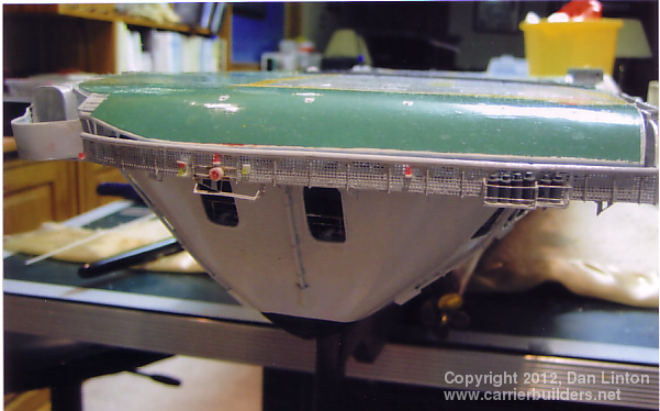
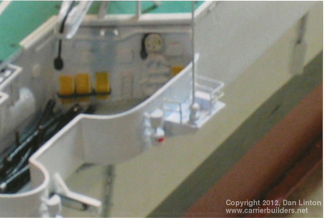
The flight deck of an aircraft carrier is a very dangerous place and all carriers have safety nets in those areas where catwalks are absent. Picture 31 above shows a strange feature of Bonaventure. A long catwalk is visible but it does not have an outside wall: instead, there is a flimsy-looking handrail and outside of that a safety net (but in this picture only the support bars are visible as the net had not yet been glued on). The netting on the Bonaventure was difficult to model. On most carriers the netting (which is rope) is stretched almost flat, having only a modest sag. On Bonaventure the nets sagged to almost a `U` shape and the edges seem to have had extra rope and thus appeared thicker. So, to try to model this I cut out strands from a sheet of plastic screen (picture 32) and then glued them to the support bars (picture 33). Picture 34 shows the area around the LSO platform: the netting comes from the type of delicate mesh used to wrap wedding candy. This was darkened with a magic marker, cut, and then glued into place. On modern American carriers deck crew wear helmets with built-in radio receivers, so the need for loudspeakers is not as important as in earlier times – but loudspeakers are still found on Nimitz-class carriers along the catwalks and on both sides of the superstructure. Bonaventure had fifteen sets of loudspeakers, two of which were on the island facing the flight deck. Pictures 35 and 36 shows the construction sequence and picture 37 shows one of the speaker sets in place along the flight deck.
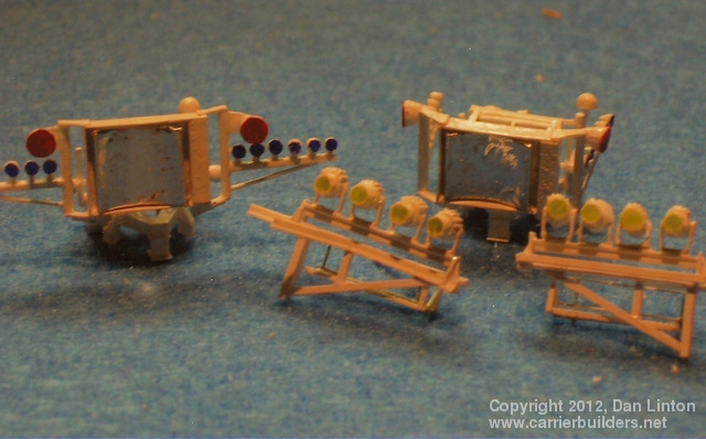
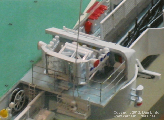
Unlike most carriers, Bonaventure was provided with two landing mirror arrays and the projecting lights associated with these early systems. Pictures 39 and 40, below, show the beginning of construction on the landing mirrors. These were quite complex: rough sea conditions required the entire array to be able to adjust, thus the complexity. This is seen in pictures 41 and 42. The letters `P` and `S` were simply my way of keeping the port and starboard structures separate, although they appeared to be identical. Picture 43 shows the mirror arrays completed, with the starboard array having its arms folded back. Picture 38, above heading this chapter, shows the port side projecting lights in place while picture 44 below shows the starboard lights folded back against the catwalk. Picture 45 shows the starboard mirror, folded, in place and picture 46 shows the port mirror array.
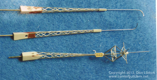
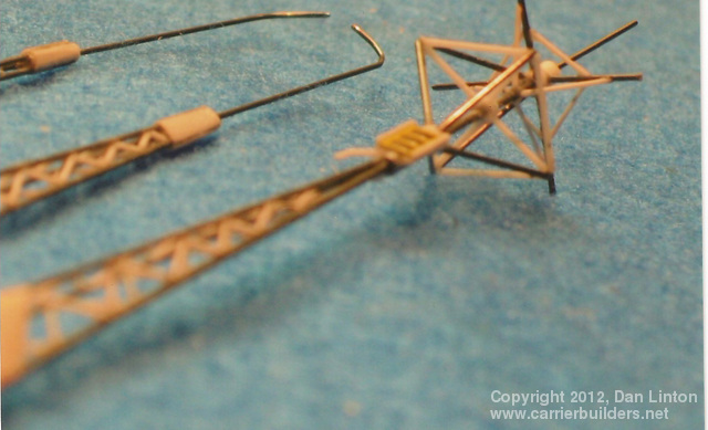
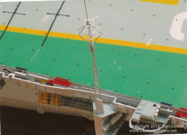
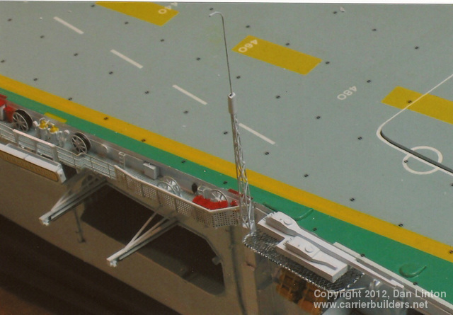
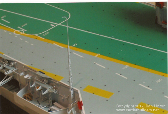
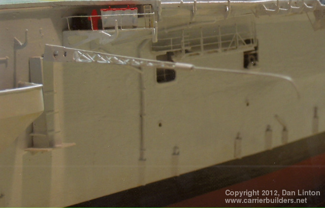
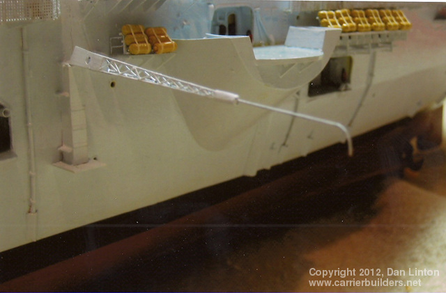
Being originally a British carrier, it is not surprising that some British equipment was maintained on Bonaventure. Picture 47, above, and picture 48, below, show the three large radio masts on the port side under construction. Picture 49 shows the large mast located near the LSO platform. This particular mast could be folded outward but was more regularly stowed alongside the catwalk, as seen in picture 50. The two other masts, seen upright in pictures 51 and 52, could only be folded outward during flight operations (pictures 53 and 54). On the starboard side, forward, was another large electronic mast. Its construction, piano wire and styrene, is seen in pictures 55 and 56. Picture 57 shows it in place. I will have to replace the long styrene pieces which are curving with wire to maintain stiffness. This particular mast is sited so far from the flight deck that it does not have to fold during air operations. However, it must be able to collapse against the hull in order to not interfere with the twin 3``50 cal. guns located on the sponson just to the rear of the mast. How this structure folded, I have no idea.
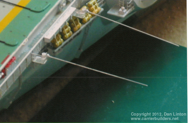
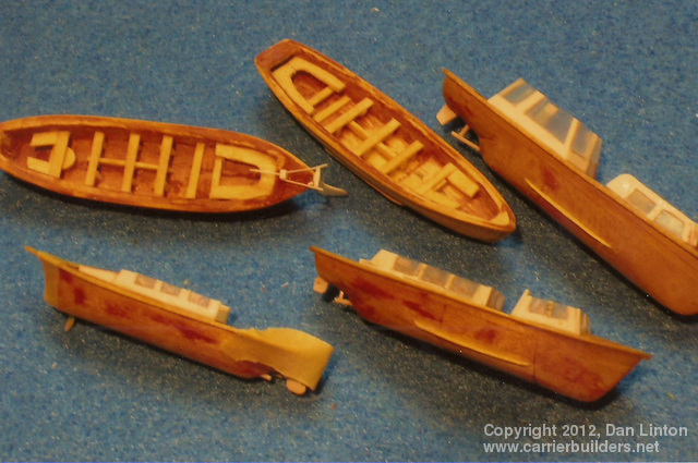
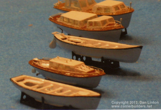
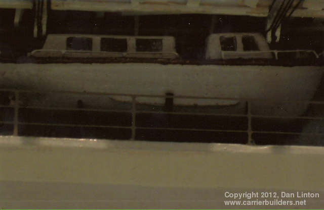
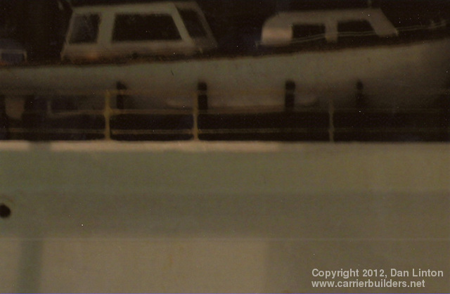
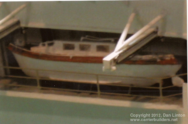
Bonaventure had eight whip aerials or antennas on its island and most can be seen in picture 58, above, particularly the three attached to the smokestack and painted black. Around the flight deck were another dozen. Each gun sponson had two platforms, one on each side, which carried a whip aerial. These were upright (picture 59, below) except during flight operations when they would be folded outward (picture 60). This pattern was also true of the aerials aft of the starboard rear gun sponson (pictures 61 and 62). The aerial directly in front of the starboard mirror array (picture 63) could also be folded outward or parallel to the flight deck (picture 64). The smallest aerial was found on a platform just outside of the crane (picture 65). Its position would not affect flight operations but its location near the crane would interfere with underway replenishment, thus it folded parallel to the flight deck. Picture 66 shows hoses, used for underway replenishment, stacked inside a sponson. Ship`s Boats: From commissioning in 1957 to its 1966-67 refit, Bonaventure had five boats, stored in deep insets in the hull. Significantly, four of these boats were eliminated and the ship emerged after its refit with only one boat and four of the insets plated over. The boats were not considered useful and they suffered much water damage in their exposed positions, particularly on North Atlantic operations. I had the choice of building the boats with covers (the easier choice) but because of decent plans (picture 67) I decided not to cover them up. Pictures 68 and 69 show the boats under construction. The next five pictures (and I apologize for their being dark), 70-74 show each of these boats in place. [note: because each chapter only allows for 12 pictures, there was not enough space for pictures 71-74: they are found at the end of the article, along with the pictures in chapter 10).
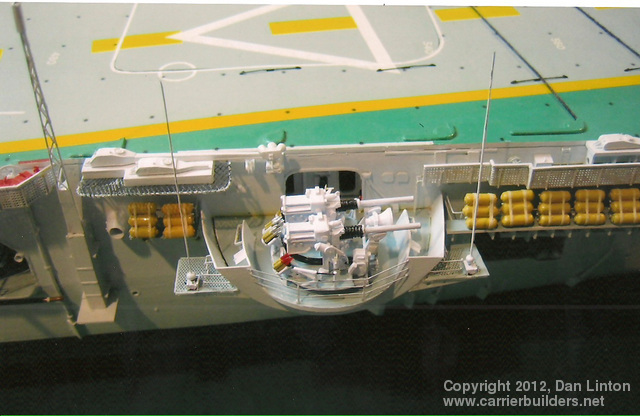
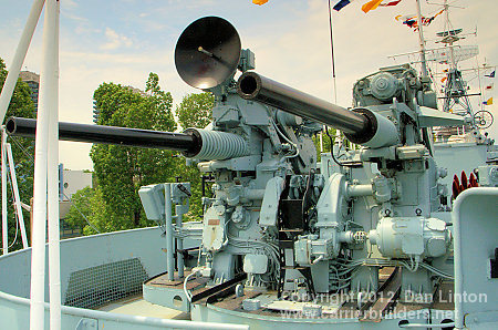
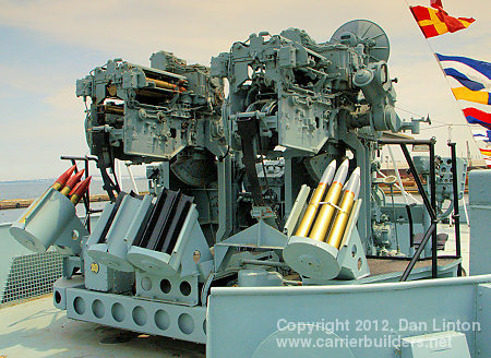
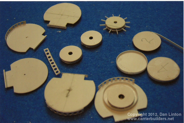
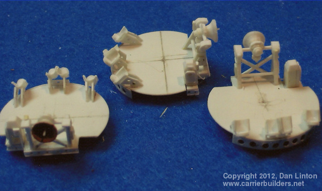
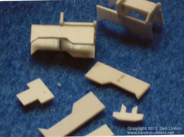
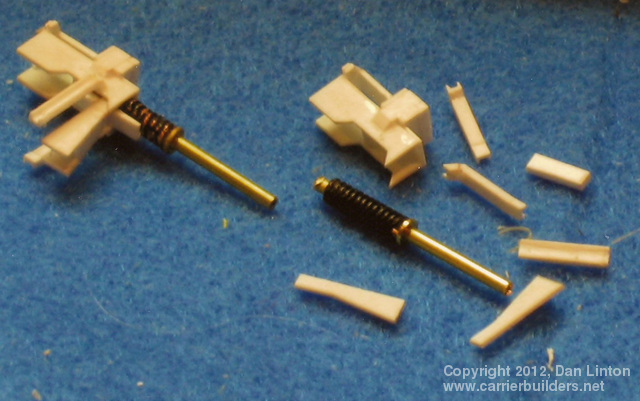
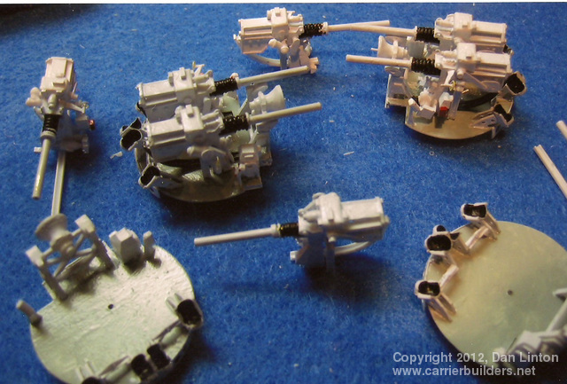
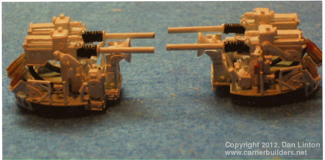
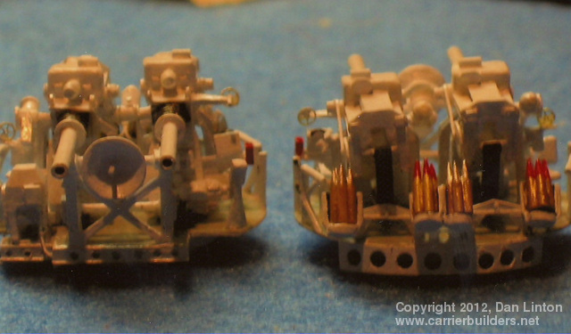
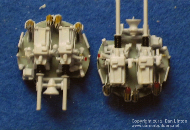
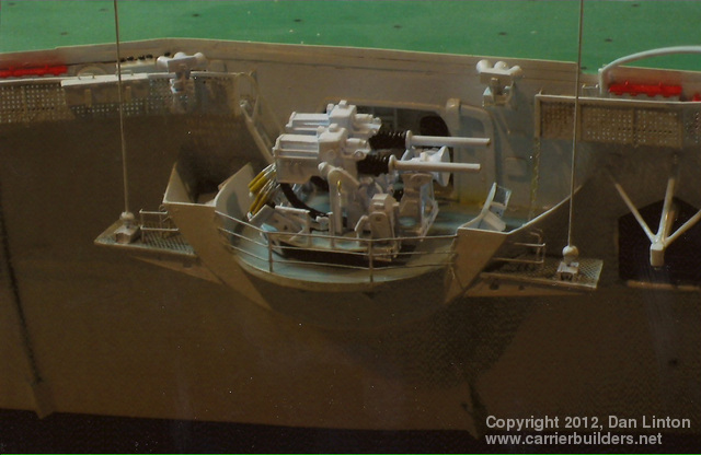
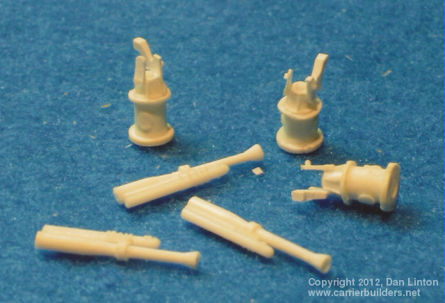
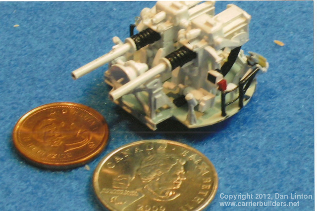
Bonaventure had four twin 3”50cal. guns, each being supported by a sponson located on each of the four quadrants. Far too light for major surface action, they were also inadequate as anti-aircraft guns for combat in the 1950’s and 1960’s. Canadian admirals wanted them replaced by surface to air missiles but these were expensive. The 1966-67 refit simply removed the foreward guns and their sponsons; the aft guns were retained. Since the guns were open mounts and quite complex (see picture 75 above and 76 below), they were the last major structures I built for this model. The platforms for the guns were the starting points. Picture 77 shows platforms in the foreground with their undersides completed. You may notice five platforms in the picture – the extra is for another modeling project. Picture 78 shows three platforms ready to receive their gun mounts. The beginning of these mounts is shown in pictures 79 and 80. The mounts were not identical: picture 81 shows the right-hand mount and picture 82 the left hand mount. Picture 83 shows progress with two platforms having their gun mounts in place. Pictures 84, 85, and 86 show completed assemblies, with handrails, seats, and shells in place. Each of these twin 3”50 cal. guns and mounts has over 280 pieces. They took a long time to complete. The last picture, 87, shows a completed twin sited on its sponson.
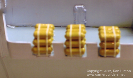
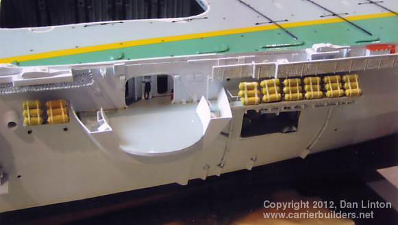
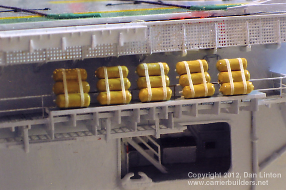
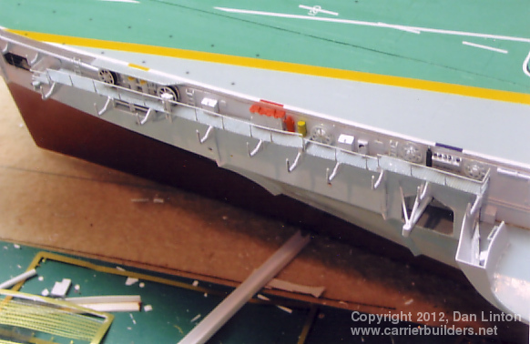
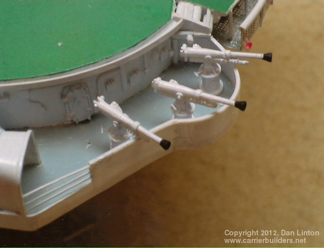
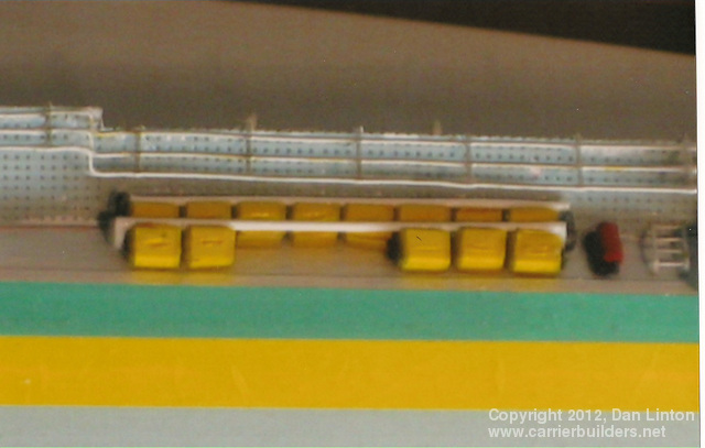
Bonaventure had three 6 pdr. saluting guns on its port side in a sponson near the aft flight deck. Picture 88 shows these guns nearing completion. In picture 89 they are complete but not painted and picture 90 (above, heading this chapter) shows them in place. Since the guns were ceremonial, they tended to be painted differently from one cruise to another. Had I wished, I might have painted the barrels black and the muzzles white. In picture 91 notice the yellow items along the edge of the flight deck. These are wheel chocks, stored here until needed. Picture 92 shows the anchor (white metal from John R. Haynes) and the depth markings on the hull. A similar series of markings will be found near the stern. The extent of these markings varied from cruise to cruise. The slight yellowing was caused by the Future acrylic I used being a bit old. I will have to deal with this before putting the ship in the water. And finally, the very last pieces to be glued on the model were the windshield wipers, seen (and you have to look very closely) in picture 93.. Next: Part 6: The Aircraft and Deck Equipment
Photos and text © 2012 by Dan Linton February 19, 2012 |