AircraftProfilePrints.com - Museum Quality Custom Airctaft Profile Prints
After the disaster we know as World War I but which men and women of that time called The Great War, it was in everyone’s interest to avoid another arms race. The call for a ‘Battleship Holiday’ met a positive response, and considering that the major participants – Britain, France, the United States, Japan, and Italy – were all on the winning side, there was no legitimate threat that could be used as a reason for not limiting naval arms. But nations have particular interests, and in the case of Japan, which had participated the least and suffered the least from actual combat, there was a deep underlying feeling that, in part, motivated her response. She was asked to undertake restrictions by white Europeans that would, at least as long as the Treaty terms lasted, make an inferior position permanent. Her world-view [see Part 6 of this series] foresaw an eventual expansion in search of resources and markets that might well lead to a confrontation with the United States, or Great Britain, or both. The British had possessions in every ocean on earth, the largest merchant marine, and the largest navy on the planet; the Americans had two large ocean fronts plus the Caribbean to the south and had publically stated they would build a navy as large as the Royal Navy – and Japan could never build up to these levels even had they wanted to. But what level of restriction would be consistent with both honour and national interest? For many in Japan, and particularly in the armed forces, any restriction was dishonourable. For the government of the day, a naval force level 70% of the British and Americans was the goal, but 60% would be acceptable if the British, and particularly the Americans, agreed not to fortify the bases they already had in their Pacific possessions for the duration of the Treaty. When this was agreed to, the formula of 5:5:3:1.75:1.75 (British; U.S.; Japan; France; Italy) became the operating mathematics for the next ten years for all types of naval vessels. For carriers, although limited to 23,000 tons maximum per ship, an exception was made for both the U.S. and Japan. The Americans could convert two partially built battle cruisers into aircraft carriers and these became USS Lexington and USS Saratoga. The Japanese could also convert two battle cruisers into carriers and these would bring forth all manner of problems and possibilities for the Imperial Japanese Navy.
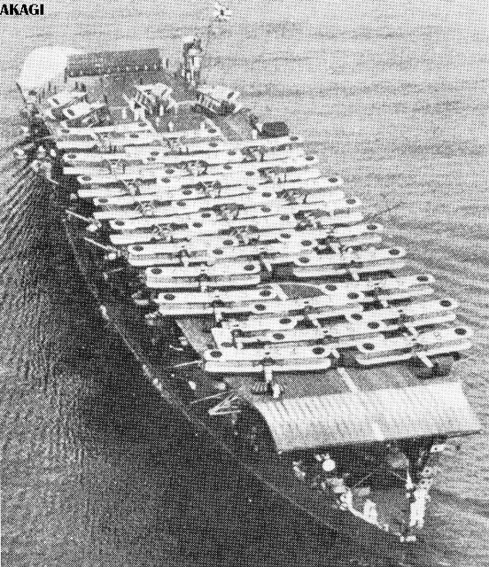
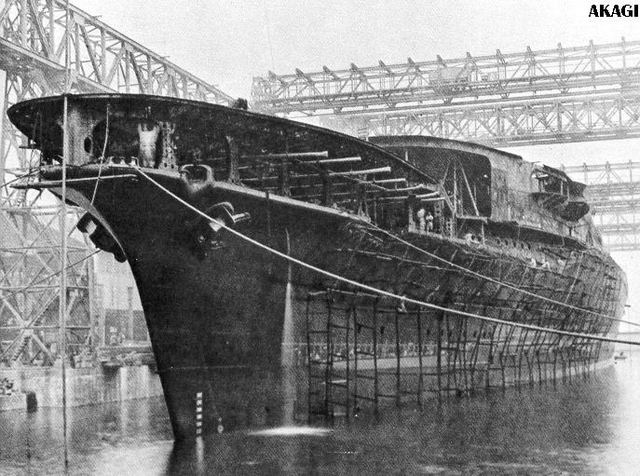
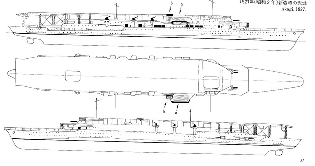
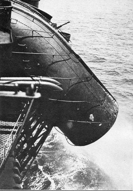
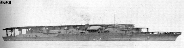
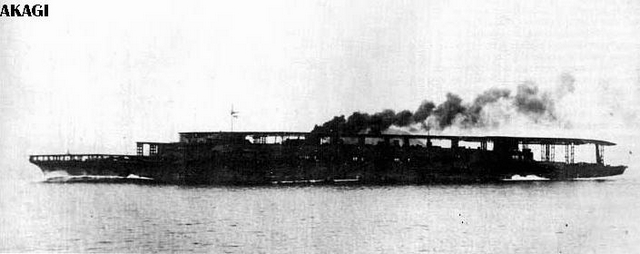
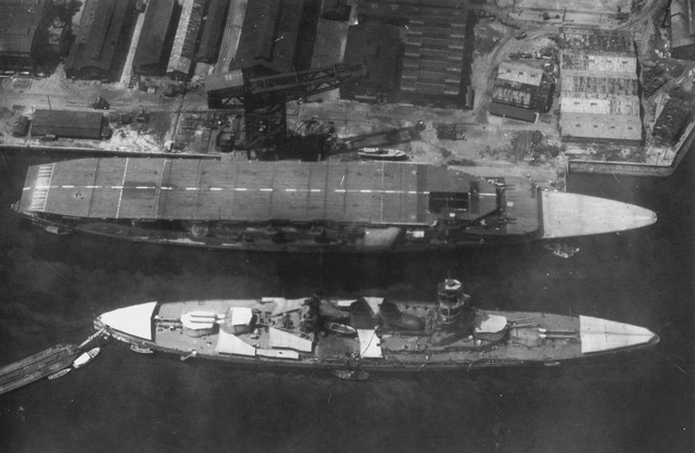
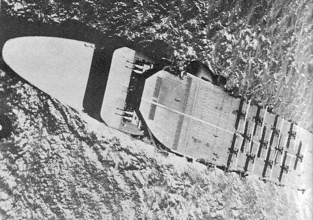
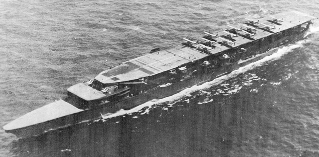
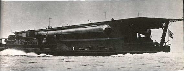
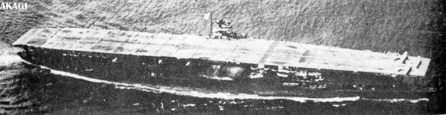
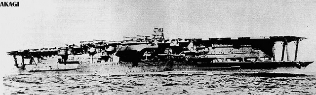
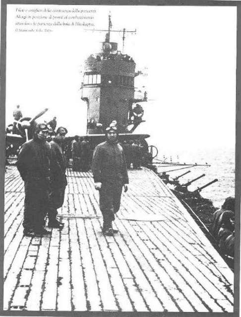
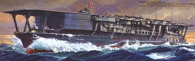
IJN Akagi (‘Red Castle’ in English) has become the best known of all of Japan’s aircraft carriers. Originally a battle cruiser, she was under construction for eight months before the order came for her to be completed as an aircraft carrier.(picture 1 above) She would displace over 30,000 tons; had 10- 8”guns (the maximum the Treaty would allow for carriers) and 12-4.7” guns; and could carry 60 aircraft. (1) Her armour belt was lowered and thinned from the original battle cruiser specifications and the torpedo bulges changed to enhance stability for Akagi, following British practice, had a double hangar deck.(picture 2) Not following British practice, but developing a system uniquely Japanese, Akagi rid herself of stack gases by means of one large funnel canted downward. (picture 3) This was on the starboard side and water was often sprayed as the smoke left the funnel, making it heavier so that it would not roll up and over the flight deck and thus interfere, particularly with landing operations. (picture 4 – but it is Kaga’s 1930’s reconstructed funnel that is shown) Akagi was built with three ‘flying-off decks’ (going the British one better as the reconstructed HMS Furious of 1926 had only two). The upper or main flight deck was 624’long (192m) and slightly humped amidships; the middle flight deck, leading directly from the upper hangar was only 60’ (18m) and was to be used by the lightest planes; and the lower flight deck led directly from the lower hangar and its 160’ (49m) was considered sufficient in 1927 for torpedo bombers to take off. (2) (pictures 5, 6, and 7) The two hangar decks were quite long and there was even a third one, small and used for storage of disassembled aircraft, towards the aft end of the ship. As originally constructed, Akagi had only two elevators and was a ‘flush-decker’. It wasn’t long, however, before a very small island was added on the starboard side and used primarily for ship navigation (see the picture that begins this entire article, and also picture 7) (3). With her guns, equivalent to that of a heavy cruiser, Akagi joined the fleet in 1927.(picture 8) It was not long before the Japanese discovered, as would the British, that multi-flying off decks were a design error for the increase in aircraft size and engine power made them useless. (pictures 9 and 10) The British never corrected the design flaw in the ‘three sisters’ (Furious, Glorious, and Courageous) but the Japanese would thoroughly modernize Akagi in the 1930’s.
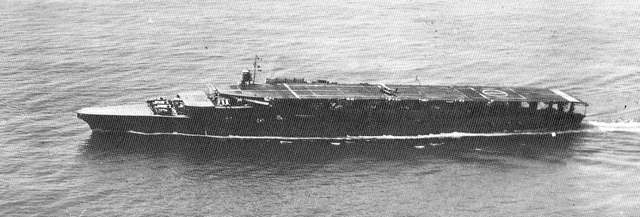
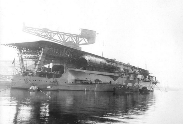
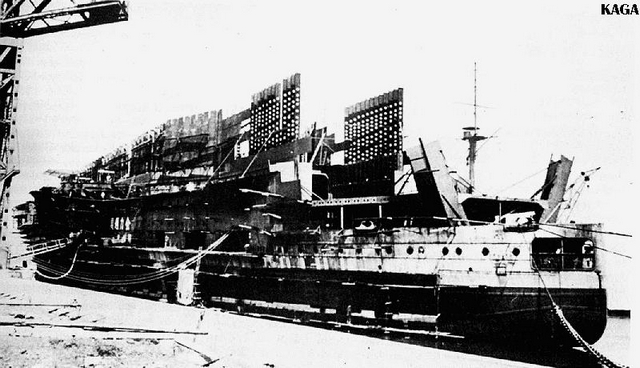
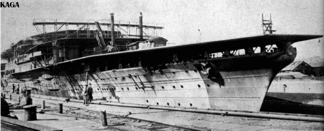
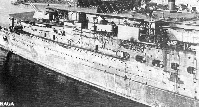
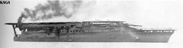
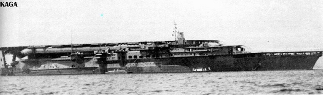
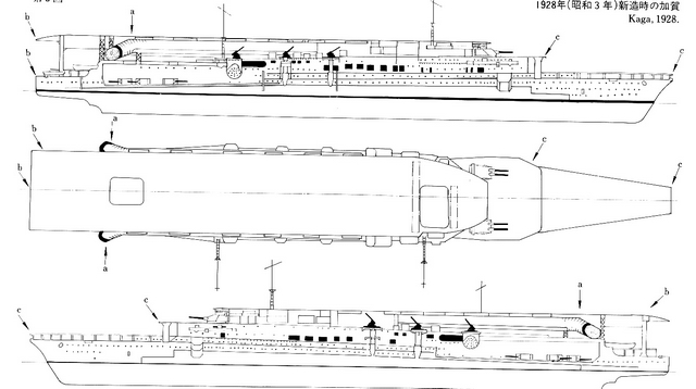
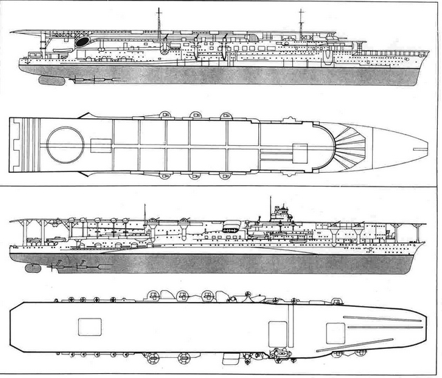
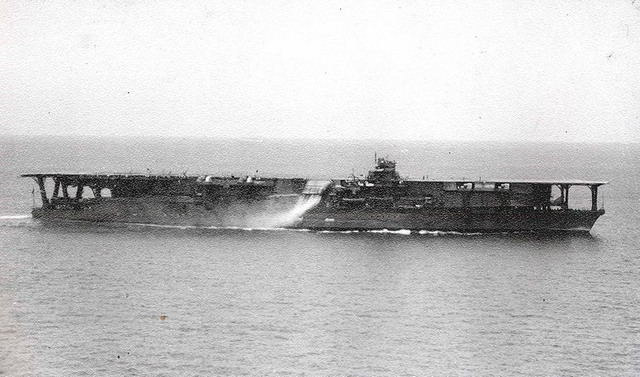
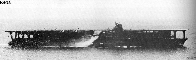
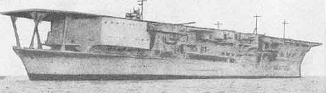
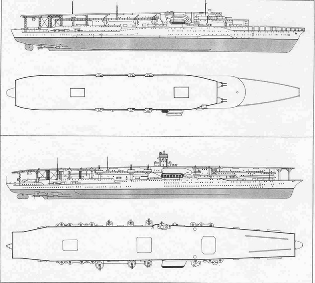
The battle cruiser Amagi, a sistership to Akagi, was scheduled to be Japan’s second capital ship converted into a carrier but the great earthquake that struck Tokyo in 1923 so damaged Amagi’s hull that it was scrapped and in its place was substituted the hull of the incomplete battleship Kaga (the name of an old Japanese province). Kaga was to have displaced 39,000 tons as a battleship but her conversion led to a carrier of 27,000 ‘official’ tons (in reality, over 30,000). Shorter by 60’(18.4m) and wider than the battle cruiser hull that Akagi was built on, Kaga was not truly a sister ship. She could make only 28kts and her funnel arrangements imitated that of HMS Furious (and proved to be equally unsatisfactory), being long tubes passing along the sides of the ship under the flight deck level with the exhaust outlet canted downward and outward. These are clearly seen in picture 11 above and in picture 12 below. Her main flight deck was 64’ (19.6m) shorter than Akagi’s but was perfectly horizontal. She too had double hangars, three flying off decks, two elevators, and was a flush-decker with 10-8” guns and 16-4.7”guns.(4) (pictures 13, 14, 15, and 16). She too, had a temporary and tiny island added to the starboard side (picture 17) but it would disappear soon after Kaga joined the fleet. (picture 18) It is interesting to see in the pictures of Akagi and Kaga how prominent the 8” gun turrets are on the second flying-off deck but how unfortunate their location was compared to the clear arcs of fire that similar 8” gun turrets on Lexington and Saratoga enjoyed. Kaga commissioned December,1928 and like Agaki would undergo within a few years a thorough reconstruction that would improve operating procedures, and, as importantly, boost the number of aircraft she could carry to match that of the American giants. Kaga was taken in hand in 1934 and emerged in 1935 a modernized carrier. The changes are clearly seen in the picture 19 diagram. She was given a single flight deck that measured 812’ x 106’ (250m x 32.6m) and all her hangar spaces were enlarged. The hull itself was lengthened so that she might still retain her 28kts despite the addition of over 8000 tons of displacement. A third elevator was added forward. An equally significant change was the removal of the long funnel tubes in favour of a single large funnel amidships on the starboard side canted outward and downward as on Akagi (picture 4 above and picture 20) Her anti-aircraft battery was improved but in a move objected to by Admiral Isoroku Yamamoto, she retained all ten of her 8”guns. The twin turrets were removed and the barrels mounted as singles in casements in the same gallery as the other six: here, so close to the water and near the stern of the ship, they would be useless. The Japanese navy, no less than the American, had admirals who saw carriers as cruisers that happened to carry airplanes. (5) Kaga could now carry 90 aircraft (72 plus 18 disassembled reserves) and she rejoined the fleet late in 1935.(6)(pictures 21 and 22)
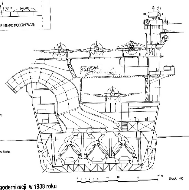
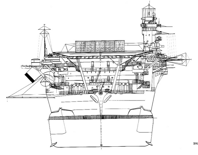
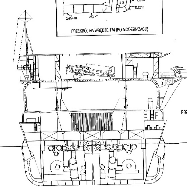
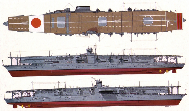
Akagi’s reconstruction was later and longer than Kaga’s, a function of budget problems. She too emerged with a third elevator, more hangar space and an increased displacement that had to be compensated for by larger hull blisters. (picture 23 diagram) She could handle 91 aircraft in this new configuration. (picture 24) Modifications to her funnel were minor but its placement precluded an island being put amidships on her starboard side. (picture 25) Instead Akagi (and later Hiryu) would have a small island on her port side. The thinking which determined this was that carriers would operated in pairs (Akagi-Kaga; and later Hiryu-Soryu) and the air traffic patterns established above the two carriers for landing would be more efficient if one ‘racetrack’ served one carrier with a port side island while another served a carrier with a starboard side island. Pilots objected, however, and this experiment was never repeated. (7) The twin 8” turrets which had been on the middle flight deck were removed but, unlike Kaga, were not retained, thus Akagi had only six 8” guns, in casements near the stern and near the waterline and thus ineffective. Akagi, 855’ (263m) long and 103’ (31.7m) on the beam had a flight deck as wide, and slightly longer than Kaga’s. (picture 26) Together these two ships, along with IJN Hosho, would be used to develop warfare for the Imperial Japanese Navy.
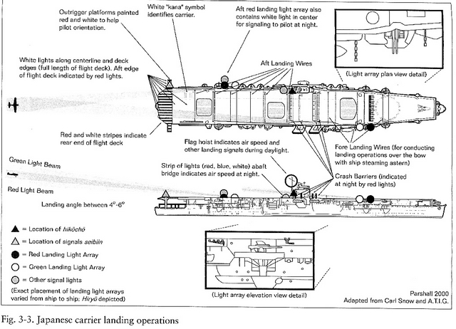
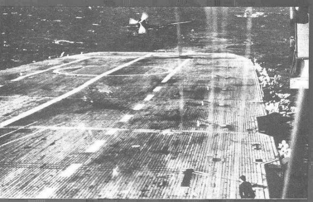
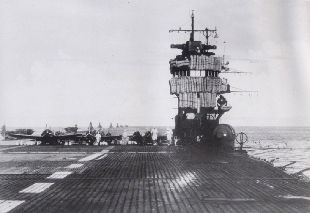
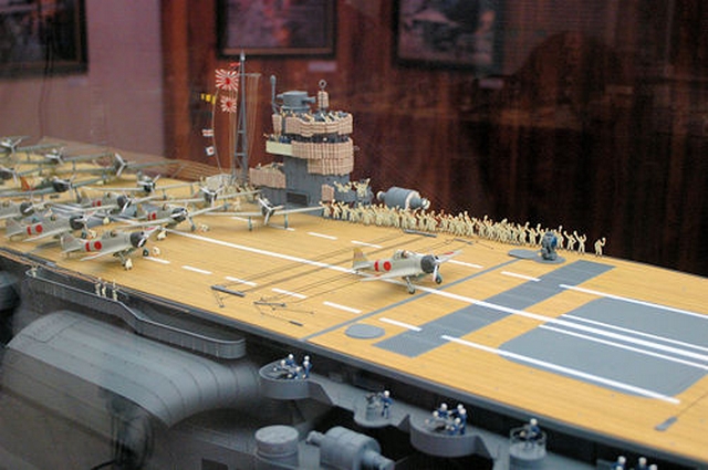
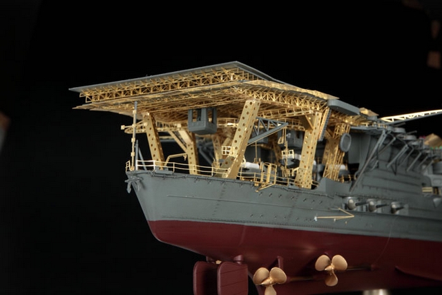
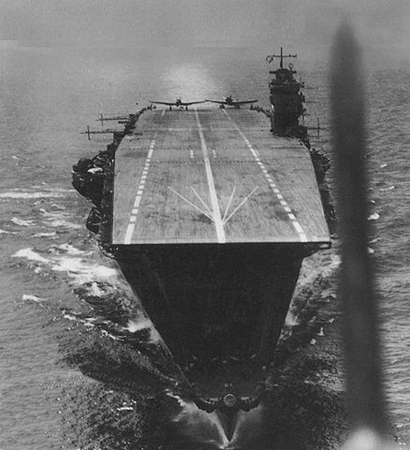
As with the Royal Navy and the American Navy, the development of carrier air power in the 1920’s and 1930’s would result in successes, failures, and passionate debates in the Imperial Japanese fleet. What emerged ultimately was, by 1941, the finest carrier force on the planet, part British in design, part American in philosophy, and uniquely Japanese in many practices. The starting point is aircraft capacity. The Japanese measured, as the British did, a carrier’s capacity by the number of aircraft that could be accommodated in the hangar. Here all the fueling, arming, and maintenance of the aircraft would take place. The flight deck was to be left clear – the American concept of the ‘deck park’ was not part of Japanese practise. Once an aircraft landed, it was pushed to an elevator and struck down into one of the hangars. The pace of landing, and also of assembling aircraft for take-offs, was determined by the elevators – how quickly they could be loaded, travel, off-load, and return. Vertical movements of aircraft, rather than horizontal, were the determining features on British and Japanese carriers. (8) Unlike British carriers, and in parallel with American practice, the flight deck was not armoured nor were the sides of the hangar: instead, the flight deck was an ‘add-on’ placed above the main deck (the ‘strength deck’), a thin steel frame onto which wood planking would be laid.(picture 27, above) Only the planking was parallel to the ship’s length, not across as on American carriers.(picture 28)(9) Beginning with Ranger CV-4, American hangars were ‘open’, roller doors being used to cut out wind and water during stormy periods; open for ventilation at other times. A bomb penetrating the flight deck would likely explode in the hangar, but much of its energy would blow away through the thin roller doors if they were closed (usually the case in battle), or pass harmlessly through, thus causing less upward damage to the flight deck. As most arming and fueling was done on the flight deck, a bomb burst in the hangar deck, although serious, was not necessarily catastrophic. The opposite was true of Japanese carriers for the sides of the hangar deck were used for storage – and of course kept out the wind and rain – and the energy of any bomb penetrating the unarmoured deck would be confined inside a closed hangar where fueling and arming took place. As was evidenced at the Battle of Midway, Japanese carriers were prone to suffer catastrophic hangar fires. (10) Fleet exercises and studies convinced the Japanese (as the Americans were being convinced) that the essence of future naval warfare was to first destroy the enemy’s carriers – and the side that struck first would win for the now-blinded fleet could be joined in battle by the main fleet’s battleships to complete the job of annihilating the enemy. Since the prospective enemy were the Americans, and their great weakness was the distance between their main bases at San Diego and San Francisco (and after 1940, Hawaii (11)) and their holdings in the Philippines and Guam, carrier aircraft and submarines could keep any possible supply line insecure. The American fleet would sooner or later have to sortie to protect that supply line and the carriers of that fleet would have to be destroyed. Thus the Japanese, knowing the dangers, came to adopt a concentration of carriers in one strike package (six at Pearl Harbour; six at Midway); came to concentrate on offensive capability at the expense of defensive measures; and purposely designed planes that could take little punishment in favour of aircraft that were lighter and could travel farther for it was necessary to ‘outrange’ the Americans both in search and attack missions. (12) This need to keep the aircraft light had some interesting consequences. With the exception of the Nakajima B5N torpedo bomber, Japanese aircraft did not have folding wings for the wing-folding mechanism would add weight and affect range. Later models of the Zero fighter, and some other aircraft, had manual folding wing-tips, but this was done to fit them better on the ship’s elevators. And those elevators, in turn, tended to be larger than those on British and American carriers in the 1930’s. A final consideration is that with lighter aircraft, there was no need for catapults and no Japanese carrier of pre-war design had them. (14) For over sixty years now aircraft have landed on a carrier’s angled deck, their pilots aided by a MLS (Mirror Landing System). Before WWII, however, the Japanese had developed a system of mirrors and lights to be used for both day and night landings. The diagram (picture 29) is almost self-explanatory. The hikocho was the air operations officer who controlled launches and landings. Since the diagram depicts IJN Hiryu (one of the only two carriers with a port side island) it might be a bit confusing. On flush deck carriers he would be on a deck edge platform amidships, usually on the port side away from the funnel. For take-offs, a white flag with a large black ball would be raised – a ‘prepare for take-off’ signal – while waving a white flag was the actual ‘take-off’ signal. The direction of the wind over the deck could be determined by pilots as steam was released from a small vent on the forward flight deck where six white lines radiated out at 10º angles. The lighter aircraft which needed a shorter deck roll took off first, followed by the heavier bombers. Take-offs were accomplished at 20 to 30 second intervals. For daytime landings (picture 30) a black ball was hoisted with two flags bearing numbers – wind velocity over the deck in meters per second. A crewman called the seibin was not actually an LSO (landing signals officer) but stood on the port side outrigger platform to raise a red flag (‘go round again’) or a white flag with a black ‘H’ meaning the aircraft’s tail hook was not down. Again, wind direction was indicated by the steam vent on the forward flight deck. The aft part of the flight deck had red and white stripes both as a warning and as a guide for lining up correctly. A centerline white stripe ran the entire length of the flight deck and had embedded lights for night landings. Many carriers had a white outline circle painted on the rear section of the flight deck in the area of the rear-most arresting wires, thus the circle was an aim point for aircraft coming in to land. (15) (picture 31, Akagi) At night the light system was imperative and even included red warning lights on the crash barriers. As sophisticated as this system was, accidents still occurred and as in the USN, plane guard destroyers always followed closely behind carriers during flight operations. (16)
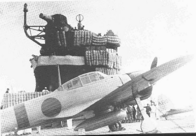
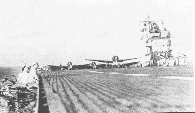
Before the advent of radar, fighters were seen to be of value only to clear out the enemy’s spotter aircraft and to protect torpedo and dive bombers along the way to their targets: defending the carrier itself had a low priority. Combat Air Patrol had little value unless it was definitely known that an attack was coming and even then it could only manage to destroy or deflect some, but not all, of the attackers. And with their unarmoured decks, a carrier in the Pacific might not be sunk but could be put out of action for a considerable period of time. (17) The composition of air wings changed with wartime experience –more fighters were carried and there were no longer more torpedo bombers than dive bombers (this early favouring of torpedo bombers reflected British practice). Akagi and Kaga together made up the First Carrier Division and led the attack on Pearl Harbour in December, 1941. Akagi’s small island festooned with temporary splinter protection (picture 32, above) is iconic: such pictures are seen in every documentary or film made about the attack on Pearl Harbour – invariably it is the crew of the Akagi cheering ‘banzai!’ as the planes roll forward and take off. (pictures 33 and 34) As flagship, Akagi was important but she was only one of six carriers that participated in the Hawaiian attack and then the strikes at Rabaul in January, 1942; followed by actions in Java in March and then the dash into the Indian Ocean and Ceylon in April, 1942. These ships returned home to Japan in May but then Akagi and Kaga were both destroyed June 4, 1942 at Midway. The degree to which the disaster at Midway was a function of bad luck will not be debated here. That is an often-told, often-argued, story. What might be suggested here is that some ships, like some warriors, seem destined to have short but glorious lives and their names live on – in poems and novels for the warriors – and in models for the ships.
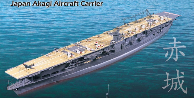
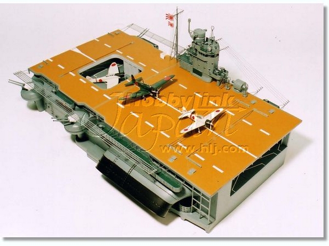
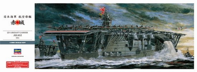
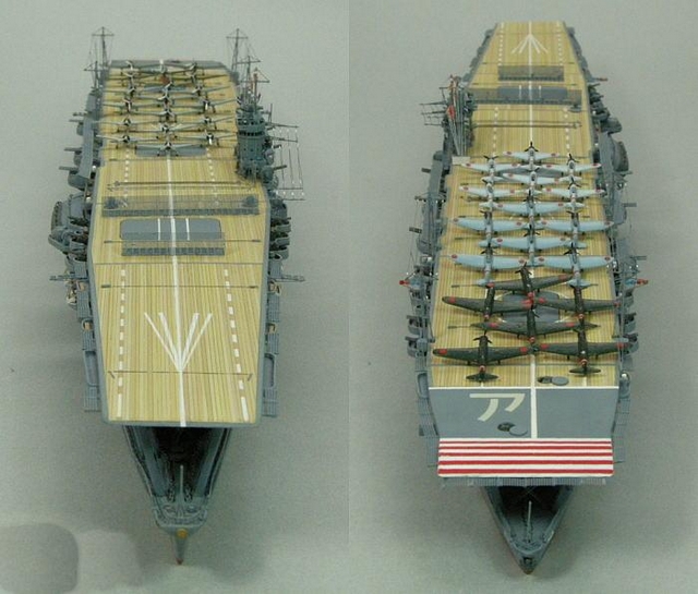
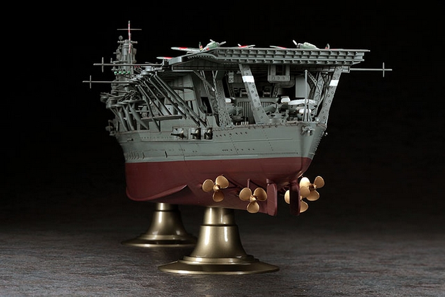
More than 200 aircraft carriers were built in the 20th century and it is likely that the one carrier most modeled is Akagi. The picture that leads off this paragraph (no.35) is the illustration of the 1:144 scale model you can purchase from Soar-Art of Hong Kong: it will cost more than a few weeks allowance. A partial 1:144 deck and island of the Akagi was released by Wing Club (picture 36) in 2006 but its production has since been discontinued. A new 1:250 model has just been introduced in Japan in an interesting way. You sign up for a magazine subscription and every month you are mailed parts for the model and that month’s issue has a CD with the instructions of how to assemble those parts. While it stretches out the pleasure of the build over 15 monthly issues, it also is not cheap. (18) In these larger scales, Taubman Plans provides a 1:144 set (RC144-AKA); a 1:200 set (TPS085) and a 1:250 set (SMC-308). Next down the scale line is a 1:300 card model of the Akagi (Flymodel). And then there is the recently released Hasegawa 1:350 kit (HSGZ25) with four dedicated sets of PE that can be purchased from Hasegawa.(picture 37) The old Hasegawa 1:450 Akagi (HSGZ13) can still be found on E-bay as it was last released in 1999. Nichimo produced a 1:500 Akagi (NCMO-5020) that was full-hull and could be ‘motorized’ (since discontinued) and re-released it (NCMO-4086) in July, 2007 to include a brass stand. Hasegawa has released no fewer than five 1:700 kits of Akagi. HSGWL-201 is the basic waterline kit while HSG30013 was its super-detailed companion (since discontinued). HSGCH 106 was the basic 1:700 full-hull kit and HSGCH 105 was its full hull plus photo-etch companion, both since discontinued. The fifth offering is HSGWL220, released in June 2008, of a waterline Akagi as a triple deck carrier. Still in 1:700, Fujimi is preparing a 1:700 release of Akagi as she was at Pearl Harbour, and Pit-Road a decade ago offered a resin 1:700 Akagi as a waterline kit and another as a full-hull kit. Pictures 38-41 show different Akagi models displayed on the www.digilander.libero.it website – but without any description of the manufacturers or the scales. And Kaga? Pit-Road (PITHM-26) in July of 1996 offered a 1:700 resin waterline kit of Kaga as a 3-deck carrier but it has been discontinued, leaving only the old Hasegawa HSGWL202 1:700 waterline kit.(picture 42) The super-detailing version of this kit (HSG30015) was released in June 2001 but is now discontinued. I could find no Kaga models in any larger scale, nor plans in any scale. Two versions of Kaga and Akagi (1939 and 1942) are offered by Neptun and Superior in 1:1250 scale metal. And finally, you can pick up for the very young at heart KAW 13447 on the Hobby Land Japan website a nanoblock (like Lego only smaller) Akagi. No scale is given. Next: Part 11: USS Akron and USS Macon: Aircraft Carriers in the Sky
1. Macdonald, S., “Evolution of Aircraft Carriers: the Japanese Developments” , p.41 2. Pettie, M.R., Sunburst: the Rise of Japanese Naval Air Power 1909-1941, pp.54-55 3. Ibid., p.55 4. Ibid., p.55-56 5. Ibid., p.57 Lexington and Saratoga did not lose their 8” turrets until the war had actually begun. 6. Numerous sources were consulted for information about Kaga’s modernization and the data they produced are all different—one even claims that Kaga was always a flush-decker, a difficult claim to sustain when one is looking at pictures of the small starboard island built on Kaga in 1935. The figures on dimensions given above appear correct (Pettie, Sunburst…; Evans and Pettie, Kaigun….; and Jentschurra, Warships of…. p.42 all agree) but Stille, Imperial…. seems to have printed Akagi’s dimensions as those of Kaga’s. 7. Pettie, op. cit., p.57 From an engineering standpoint, an island on the port side helped to counterbalance the large mass of the funnel on the starboard side. 8. Ibid., p.67 9. Stille, M., Imperial Japanese Navy Aircraft Carriers 1921-45, p. 33 10. Pettie, op. cit., p. 65 and Stille, op. cit., pp. 6-7 Avgas tanks were incorporated into the structure of Japanese carriers. Any shock might cause them to crack or leak and Japanese damage control, marginal at best, usually could not cope with such developments. 11. The major units of the American fleet were not ‘home-based’ in Hawaii until the summer of 1940, a move that appeared provocative to the Japanese but had the advantage of moving their principal targets 2500 miles closer. 12. Pettie indicates that typical American searches in WWII were undertaken at 325-360 miles while Japanese aircraft would often go out beyond 500 miles. Americans would attack from 200-250 miles away but the Japanese could launch from 300-350 miles. Page 74 13. Ibid., p. 63. Hangar decks in Japanese carriers often had white outlines of planes painted on the deck in the most efficient pattern possible and the deck crews simply pushed the correct type of plane onto its white outline and then tied it down. 14. Stille, op. cit., pp.5-6 15. Ibid., p.45 16. Pettie, op. cit., pp. 68-72. A destroyer can just be seen in picture 30 17. The Shokaku and Zuikaku, the IJN’s newest and probably finest carriers, missed the Battle of Midway because of damage they sustained during the Battle of the Coral Sea. 18. http://deagostini.jp/akg Bibliography: Evans and Pettie, Mark R., Kaigun: Strategy, Tactics, and Technology in the Imperial Japanese Navy 1887-1941, Naval Institute Press, 1997 Jentschurra, J., and M., Warships of the Imperial Japanese Navy 1869-1945, Arms and Armour Press, 1977 Macdonald, Scot, “Evolution of Aircraft Carriers: the Japanese Developments” in Naval Aviation News, Oct. 1962, pp. 39-42 Monografie Morskie 2 Akagi AJ Press 1994 Maru Special 2 Japanese Naval Vessels, 1975 no.9 Pettie, Mark R., Sunburst: the Rise of Japanese Naval Air Power 1909-1941, Naval Institute Press, 2001 Stille, Mark, Imperial Japanese Navy Aircraft Carriers 1921-45, Osprey Publishing, 2005
Main Picture: www.digilander.libero.it Akagi soon after first conversion with temporary starboard island Last Picture: www.digilander.libero.it aircraft launched from Akagi Picture 1: IJN, public domain; found on www.hazegrey.com website Picture 2: Maru Special 2: Japanese Naval Vessels p.31 Picture 3: Monografie Morskie 2 : Akagi p.27 Picture 4: Maru Special 2: Japanese Naval Vessels p.58 Picture 5: www.digilander.libero.it Picture 6: IJN, public domain; found on www.hazegrey.com Picture 7: Maru Special 2: Japanese Naval Vessels p.18 Picture 8: Maru Special 2: Japanese Naval Vessels p.20 Picture 9: Maru Special 2: Japanese Naval Vessels p.25 Picture 10: Maru Special 2: Japanese Naval Vessels p.24 Picture 11: www.digilander.libero.it Picture 12: IJN, public domain Picture 13: IJN, public domain; found on www.hazegrey.com Picture 14: IJN, public domain; found on www.hazegrey.com Picture 15: IJN, public domain; found on www.hazegrey.com Picture 16: IJN, public domain; found on www.hazegrey.com Picture 17: IJN, public domain; found on www.hazegrey.com Picture 18: Maru Special 2: Japanese Naval Vessels, p. 32 Picture 19: www.digilander.libero.it Picture 20: IJN, public domain Picture 21: IJN, public domain; found on www.hazegrey.com Picture 22: USN, public domain Picture 23: www.digilander.libero.it Picture 24: IJN, public domain Picture 25: www.digilander.libero.it Picture 26: Monografie Morskie 2: Akagi p.44 Picture 27: Monografie Morskie 2: Akagi p.27 Picture 28: www.digilander.libero.it Picture 29: from Pettie, op. cit., p.69 Picture 30: www.digilander.libero.it Picture 31: Monografie Morskie 2: Akagi, inside cover Picture 32: www.digilander.libero.it Picture 33: www.digilander.libero.it Picture 34: www.digilander.libero.it Picture 35: found on the Soar-Art website Picture 36: www.hlj.com Picture 37: www.hlj.com Picture 38: www.digilander.libero.it Picture 39: www.digilander.libero.it Picture 40: www.digilander.libero.it Picture 41: www.digilander.libero.it Picture 42: www.hlj.com
Photos and text © 2012 by Dan Linton February 19, 2012 |