|
Building a 1:144
Scale Radio-Controlled USS Nimitz  This model has been awarded to honour the exceptional work Dan has put into this model. And even more. It's not about the model only, it's also about the effort he has put in making the articles of the whole construction from the beginning. It is just simply awesome that he shared all his thoughts, the problem he faced, and the way he resolved these. All these information is very useful to anyone, who ever considered scratchbuilding a carrier. Thank you Dan for your hard work, and good luck!
This model is awarded by Editor's Choice - Excellence Award!
It was some time in the 20th century, not the 21st , that I began the Nimitz build. And as best I am able to determine, it was completed (or I declared it completed) on November 3, 2006. And what are the things I will do again, and what are the things I will not do again?
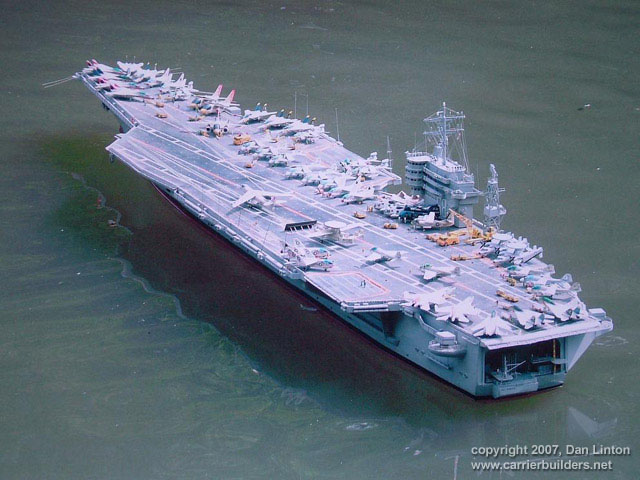
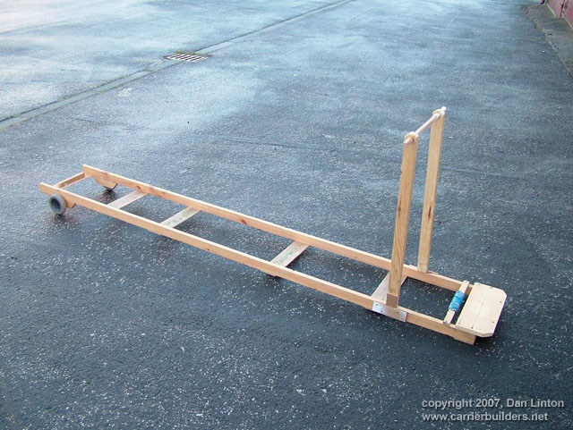
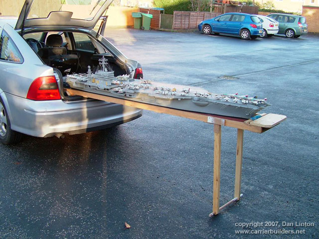
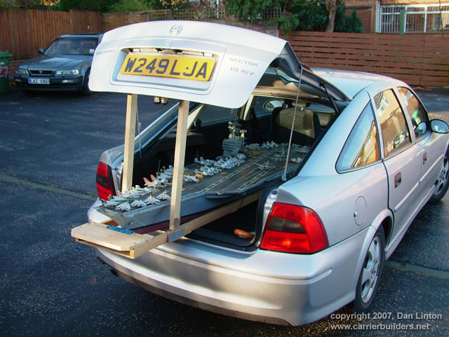
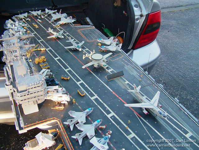
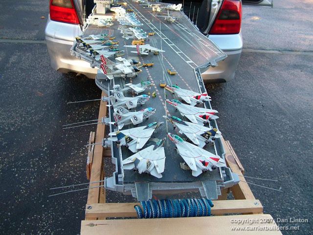
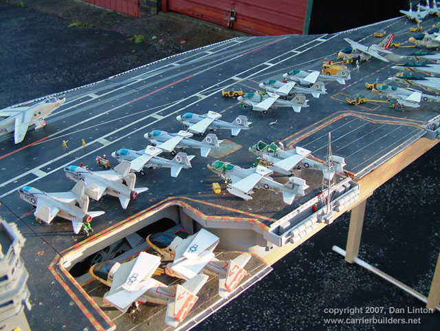
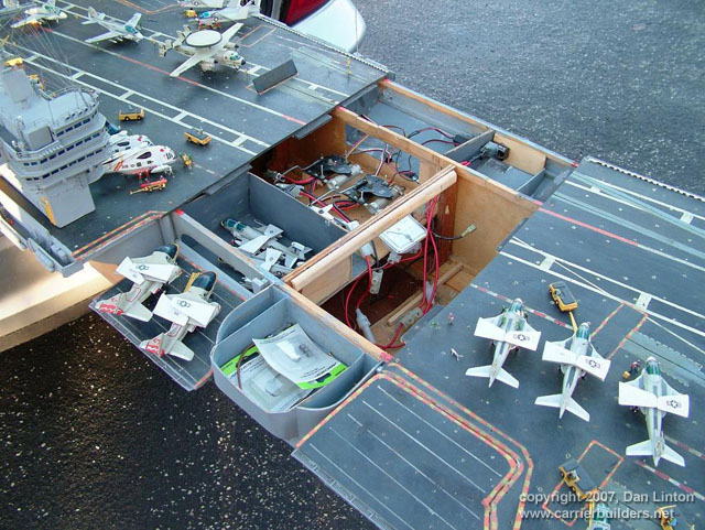
Picture 1 shows a 1:144 USS Nimitz CVN-68 in its 1975-80 configuration gliding across a pond --- but it is not my Nimitz. This model, completed a few years ago, was built by Mr. Ted Parr. I knew of its existence from a photograph or two in Model Boats magazine, and references to it with some further pictures on the ModelWarships.com website. These were sent in by Dave Wooley (author of the new modeling book Warships and Warship Modelling). I contacted Dave via e-mail and explained what I was doing in Part VIII of this build article and he provided me with Ted Parr’s phone number. I bought a long-distance calling card (Canada to England) and Ted and I had a pleasant chat for an hour, discussing our respective builds. Picture 1, and the next eleven that follow, were taken by Ted at my request and sent to Dave Wooley (Ted does not have an Internet connection), who graciously e-mailed them to me. Much of the conversation between Ted and myself dealt with philosophy – why is one building a model in the first place? Consider large scale builders and museum models: their total purpose is display, thus they are exquisitely detailed but static, having no moving parts, no changing of what is seen behind the glass. At the other end of the spectrum are the wargamers (usually 1:144 scale) where detail is sparse since the model is expected to be sunk, retrieved, and repaired to fight again, many times. Hulls, and turrets and superstructures will be dimensionally accurate but no one would bother with hand rails. Ted Parr’s Nimitz, and my own, fall between these extremes. A 1:144 scale Nimitz is 91”(2.3m), will weigh 65-85lb(30+kg) and is awkward to transport. Pictures 2,3,4,and 5 show Ted Parr’s ingenious solution to the problem of moving a large model with a small car. I think this simple device is nothing short of brilliant. And of course, Ted must be brilliant since we both started our models without good plans and each made a hull by scaling up the old Monogram 1:800 Nimitz, --- and both finished by using Aber hand-wheels (fret SV-7) for our fuel hose reels (even though they have only 5 spokes instead of the correct 8). The next three pictures – 6,7, and 8 –show the model on its carrying rack and shows a design choice: all the aircraft, crew, and the superstructure and radar tower are glued into place. In the tug of war between display elements and ‘working’ or radio-control features, Ted’s decision was to emphasize the ‘working’ or ‘sailing’ qualities of the model. Ted’s access to working gear is through a section of the flight deck (Pictures 9 and 10) and he chose not to have a full hangar deck. Some features are as ingenious as the traveling rack: for example, over 300 crew populate his model. They are beads of solder solidified onto wire and painted: close-up they appear not fully 3-dimensional but move back only a foot or two and there exists a crowded deck (Picture 11). Picture 12 is another shot of Ted’s model on the water. Ted gets out to a nearby pond for sailing more often than I can (that’s a function of climate: southern England is much milder than southern Ontario) and so to design with ‘good sailing qualities’ foremost makes sense. You can’t see it in the pictures but Ted’s model has two motors connected directly to two shafts: otherwise, it is a totally faithful and excellent scale model with superb details.
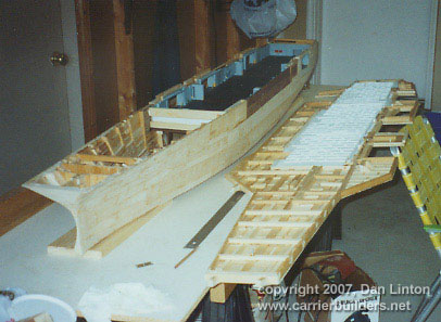
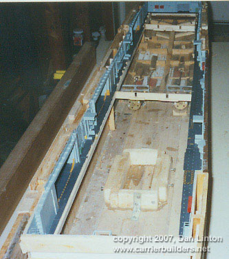
In the tug of war between ‘display’ and ‘working’ elements, my build was different from Ted’s. I assumed that I would only take the model out about three or four times in a short summer season, thus ‘display’ would dominate over ‘working’ or ‘sailing’ features. Nonetheless, I designed the model so that the entire flight deck was removable since I didn’t want gaps in the flight deck which would only become more visible over time and repeated use (Picture 13). But I still had the floor of the hangar deck to remove to gain access to the running gear (Picture 14).
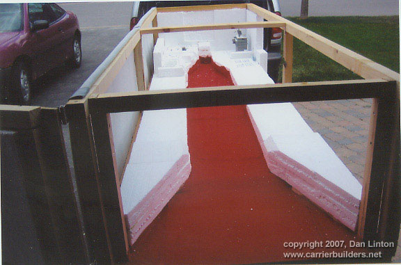
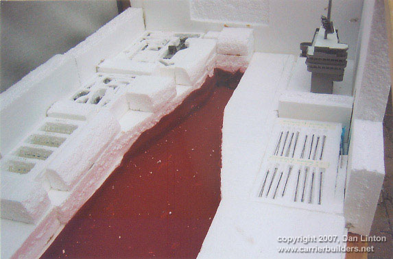
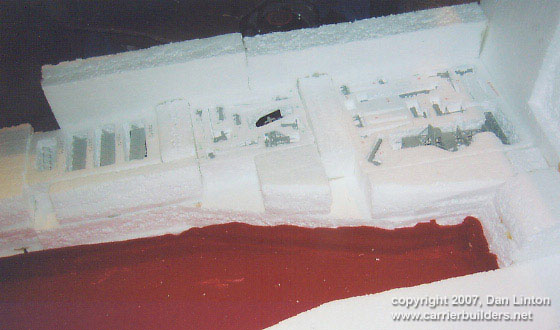
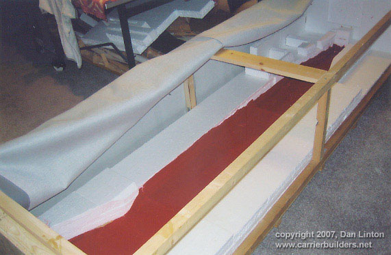
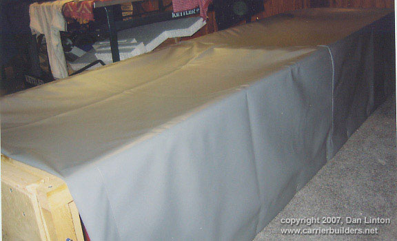
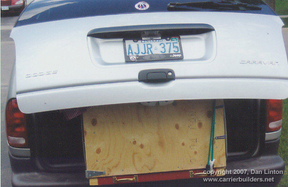
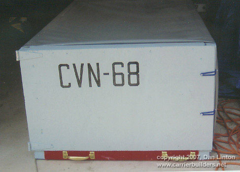
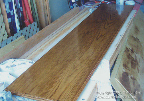
LESSON #1: do not design a flight deck to be totally removable - unless it is 40” (1.1m) or less. A 91” flight deck is too long and the shape is too awkward for easy handling: it takes two people to remove the flight deck. I intend to build other carriers and will experiment with separating the hull at the water line: my next radio-controlled effort will be 58” or 1.4m long and if it works than I will try it on larger future carriers, such as an 87”or 2.2m USS Ranger CV-61. LESSON #2: minimize the work in the hangar deck. I learned this lesson during the build and became less and less ambitious and detailed over time. In a sense I was lucky that the new CD’s (particularly those from Ray Bean) arrived after I had done the major work on the hangar deck --- otherwise I would go detail crazy and still be working on the model. LESSON #3: pay the price and do the work now. Ted Parr’s Nimitz goes from the pond, to his car, and then into a shed/workshop: it never goes in his house. My garage becomes a workshop from late April to early October, but once temperatures dip below 15C (60F) then painting and gluing are no longer possible and the model has to be brought into the house (as I write this it is mid-January 2007 and last night’s temperature was –16C). So the model has to be transported in and out of the house by hand (a two-person job) and a separate carrying case was built for it to transport it by vehicle to a pond. Picture 15 shows this carrying case – 8’x2 ½’ x 1 ½ ‘(2.5m x 76 cm x 45 cm). The model slides into the case bow-first along the red felt, kept in place by the white styrofoam blocks. Pictures 16 and 17 show that other styrofoam blocks have been used to carry antennas, JBD’s, and elevator cables. The unfinished superstructure is seen here but once it was detailed and rigged it had to have its own separate carrying case. Pictures 18 and 19 shows the heavy canvas covering for the box. My wife bought this and sewed it for me: it was stapled to one side of the box permanently and on the other side wide-head wood screws, left about ½ “(1cm) above the surface, act as ‘buttons’ since my wife sewed in buttonholes on the removable side of the canvas. Picture 20 shows the box in my mother-in-law’s van (she called the box a ‘coffin’ because of its size, shape, and the red felt). This year I expect to buy a small two-wheeled trailer to tow the box. Picture 21 shows the box painted and labeled. Since the Nimitz class are the largest warships ever in length and beam, and since I will stay with 1:144, I now have a box that can carry any future model I might build. That is the reason, being an optimist, that ‘CVN-68’ is not centered on the box door: there is room for other designations.
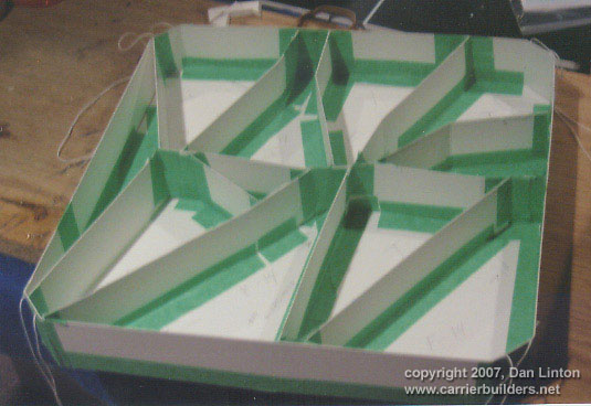
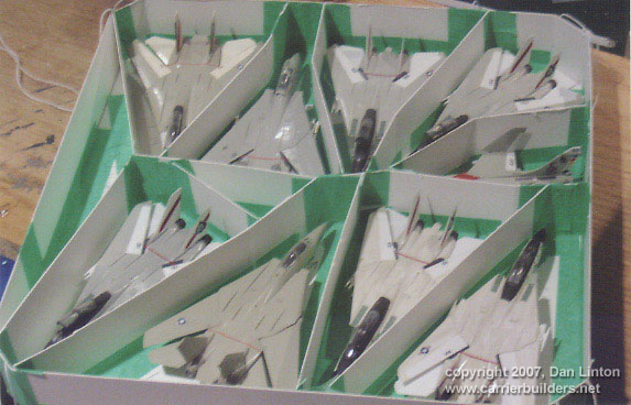
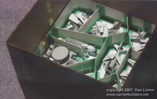
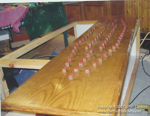
Pay the price: because I wanted to be able to display and ‘redisplay’, then the aircraft and flight deck crew and machinery could not be permanently glued to the model. Thus I needed some way of carrying these pieces. Picture 22 shows a ‘tray’ built of cardboard sized to hold various aircraft and Picture 23 shows eight F-14’s and one A-7 in one of these trays. Altogether, six trays slide in one carrying box (Picture 24 shows the box with five trays already inside). So, to take my model of the Nimitz to the pond involves loading the ship into is ‘coffin’ with all the antennas, JBD’s and cables in their separate small packs; putting the airwing into its trays and those trays into a box; putting the superstructure into its own box; and transporting everything to a pond. And then taking everything out, attaching and placing everything on the ship, and finally putting it in the water. It takes Ted Parr about 10 minutes to get unloaded and have his model running. It will take me more than an hour to get ready once I have arrived at the pond.
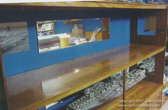
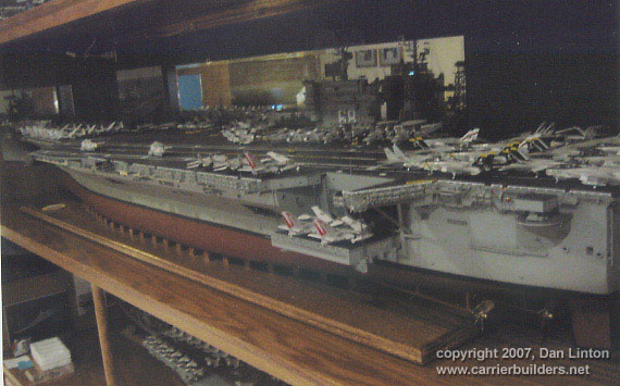
Pay the price: from October to May my Nimitz is inside the house. Picture 25 shows the display board for the model and Picture 26 shows the drydock blocks for the model to rest on. Picture 27 is pure vanity – there are two of these, at opposite corners of the display board. I am lucky to have enough space in my basement for the display are seen in Picture 28 (the 1:192 Kennedy is seen in the bottom area). Picture 29 shows the completed Nimitz ‘at home’.
LESSON #4: forget lighting. Picture 30 shows faintly the superstructure lights on. I had intended to light up the ship’s numbers ‘68’ and had toyed with the idea of lighting up the hangar deck and the runway lights on the flight deck. I decided, however, that the time and trouble involved is not worth the coin. I have two rotating radars and if I had the talent to make working elevators and/or JBD’s I might be tempted, but not lights. I now many other modelers do wonderful jobs with lighting but its not for me.
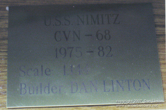
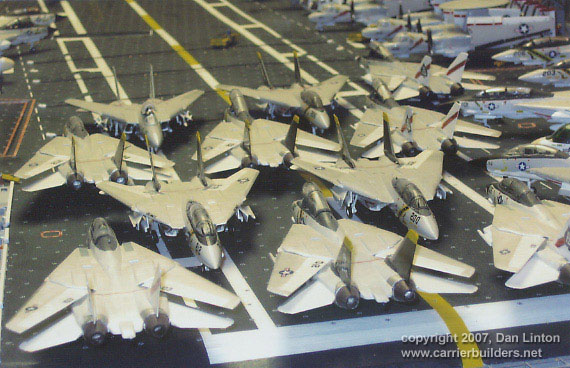
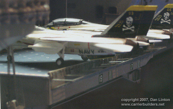
LESSON # 5: restrict ambitions. This lesson not only applies to lighting, but to another idea. If you look again at the plaque in Picture 27, you will see 1975-82. I designed the model so that it could display a scene that would be accurate for any point in those years. Even in this I was not 100% successful. From 1975 to 1977 the Nimitz had no lights inside the superstructure numbers ‘68’ and the twelve double antennas around the superstructure were shaped like cow’s horns rather than looking like television antennas. Otherwise, the model is reasonably accurate but at the cost of building more aircraft than is usually necessary. Picture 31 shows a number of F-4 Phantom II’s (from three different squadrons) at the flight deck stern that are only accurate for the first two cruises, as is the case for the RA-5C Vigilante. I have an extra SH-3 and an extra E-2C as well. In the future, only the aircraft from one air wing during a particular cruise will be done (or so I tell myself now).
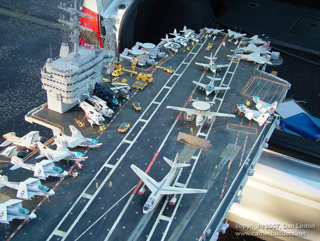
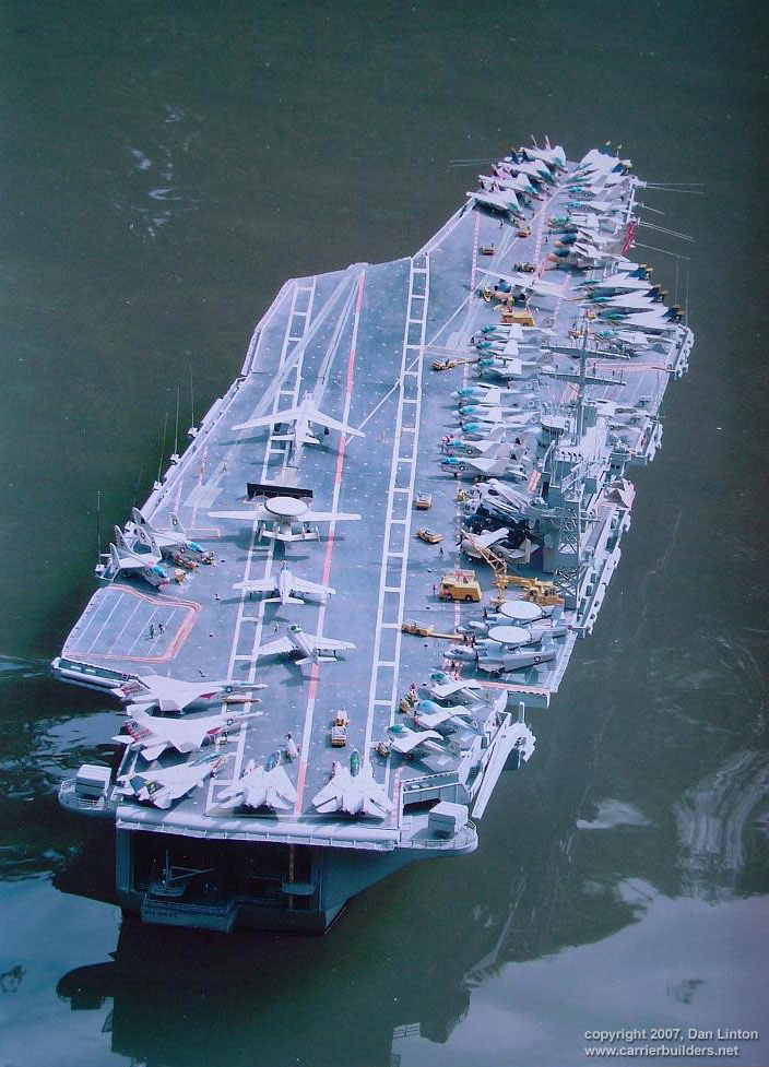
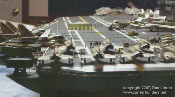
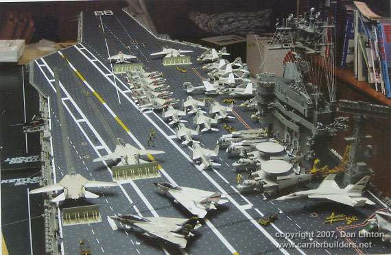
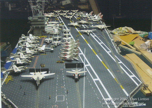
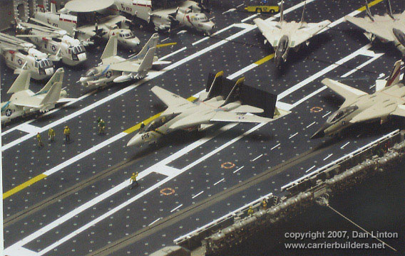
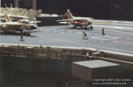
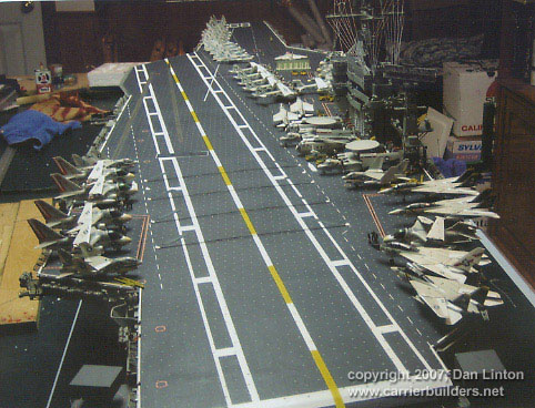
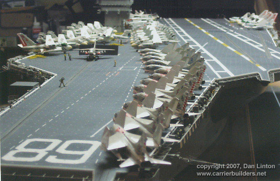
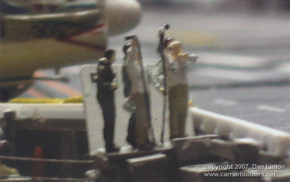
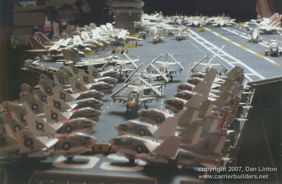
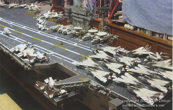
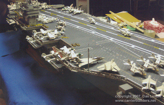
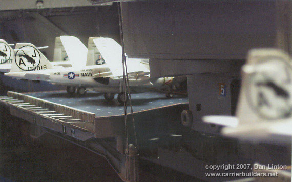
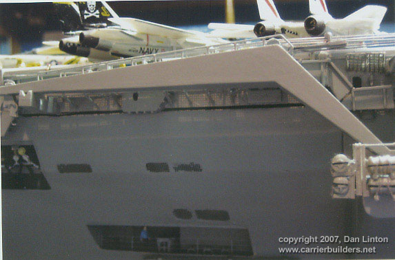
LESSON #6: don’t glue anything to the flight deck. I think I was right to take this attitude, even though it complicates the transport and set-up at the pond. At www.navysite.de will be found an article “The Arrangement of Planes on the Flight Deck”. This article distinguishes, for American supercarriers, five typical arrangements for the air wing on the flight deck. I have imitated some of these on the Nimitz. Pictures 32 and 33 show the ‘Launch Only’ arrangement: all four catapults are in use and no landings can take place. Picture 34 shows the same scene: the crew along the catwalks are glued in place but on the flight deck the crew members are standing on thin plastic strips, each painted to blend in with the flight deck. These are seen in Picture 35 – what appears to be shadows under each figure is in fact a piece of the painted plastic. A ‘recovery only’ arrangement has the bow packed with aircraft and the area in front of the superstructure and elevators # 1 and # 2, with the landing area clear. Picture 36 shows the ‘Flex Deck”: landings can take place at the same time as the #1 catapult is about to launch an A-7. Picture 37 shows the same arrangement only from the reverse angle. Although blurry, Picture 38 shows a collection of officers at the LSO platform: they are put in place, or removed, as a group of five. The windscreen behind them can be rotated up or flat on the model. The ‘Alert Five’ arrangement has the entire bow full of parked aircraft and the area beside the superstructure and elevators # 1 and # 2 but the landing area is clear of parked aircraft. Helos, an E-2C Hawkeye, an S-3 tanker, and two F-14’s are ready for launch in five minutes: one aloft, the landing area is then kept clear. The final arrangement is the ‘Locked Deck’, usually found during port visits. This is seen in Pictures 39, 40, and 41. It wasn’t until long after the photo shoot that I noticed one of the E-2C’s was dragging its tail. Only in the ‘locked deck’ arrangement in port with the antennas around the flight deck go up, thus it makes for a good display as it maximizes the numbers of aircraft that can be put on the flight deck. Picture 42 shows a ‘locked deck’ but a slightly different arrangement than Picture 39. First of all the elevators are down in Picture 42 and second, Picture 42 has the ‘Belknap’ or ‘Kennedy pole’ in place at the edge of the flight deck (its not seen in Picture 39). The Nimitz did not get its pole until 1981 (it is not seen in the movie The Final Countdown, shown in late 1979). Pictures 43 and 44 show this pole in more detail. It can be replaced by hand. Not gluing anything to the flight deck does mean that aircraft, tractors, and other deck equipment had to be made as heavy as possible: otherwise, a stiff wind can turn them into fish food in any pond
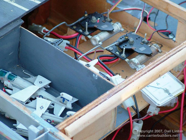
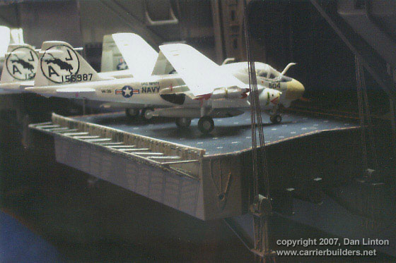
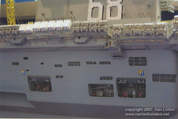
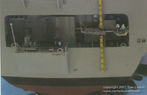
LESSON #7: decide about the elevators - either all up or all down or some combination and then glue them. Nimitz-class carriers have such complicated systems (see Part VI of the build article for more details) for their elevators that it proved not really worth the trouble to make them displayable up and down as I did. Picture 45 shows elevator #1, Picture 46 shows elevator # 2, Picture 47 shows elevator # 3, and Picture 48 shows the port side elevator #4. A workable elevator in this scale is beyond my abilities.
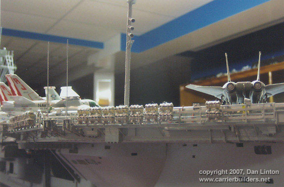
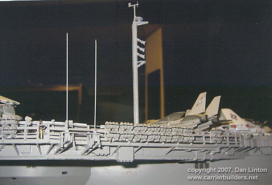
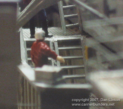
LESSON # 8: more crew. I had five packs of Preiser’s 1:144 NATO pilots
and ground crew (18 personnel per pack) and used half on the flight deck and
half on the catwalks and other areas. However, the model still looked
lifeless. Picture 49 shows the area below the superstructure but there is
only one crew member here (under the ‘11’) and there is only one crewman
seen under the crane (Picture 50). There are over 6000 sailors on a
Nimitz-class ship so Ted Parr’s 300+ strikes me as a good minimum. Picture
51 shows two figures (you can only see the legs of one of them) on a port
catwalk: ideally there should be five or six figures here. And even when
there are three or four figures, as in Picture 52 of the stern, the ship
still looks empty.
FURTHER THOUGHTS: should I weather the ship and the aircraft? Just the aircraft? Neither? I haven’t done weathering, in part because I have neither the talent nor the experience with it and feared making a mess. And I suspect that running it, even if its only a few times a year, will begin to make the model show wear and tear – but not rust. And I think I will add a Part IX to this build article called ‘Running’ and have a few shots of the Nimitz on the water with its completed superstructure and large numbers of aircraft and deck equipment placed on it. It will be the shortest of all the parts of this build article.
Go to: Photos and text © 2006 by Dan Linton July 13, 2007 |