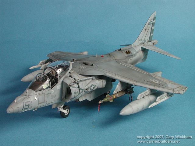
Update: 13 Apr 2005
A while since the last update. Work and other distractions have kept me
away from the bench. In the last week I've made some progress in bringing
the fuselage, wing and LEX together. I have to say that if you want to
do it properly, this requires a bit of effort. In particular the wing to
LEX join has to handled carefully requiring new panellines to be added.
This trouble is as a result of Hasegawa designing the kit as very modular
(so they can give us as many variants of the Harrier II as possible).
I've also decided how I want to setup the display base for this model.
As a result I've started painting some figures. Please don't laugh when
you see them :( I'm not a figure modeler. The other day my order of a set
of PE carrier deck tie down points from White Ensign Models arrived. |
 |
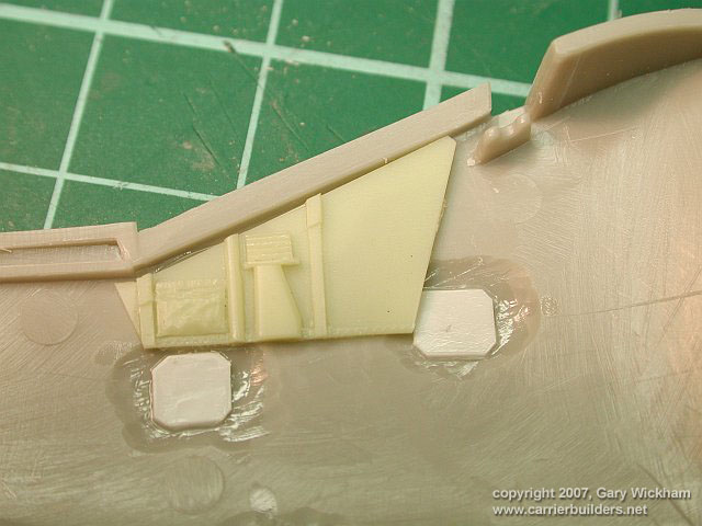
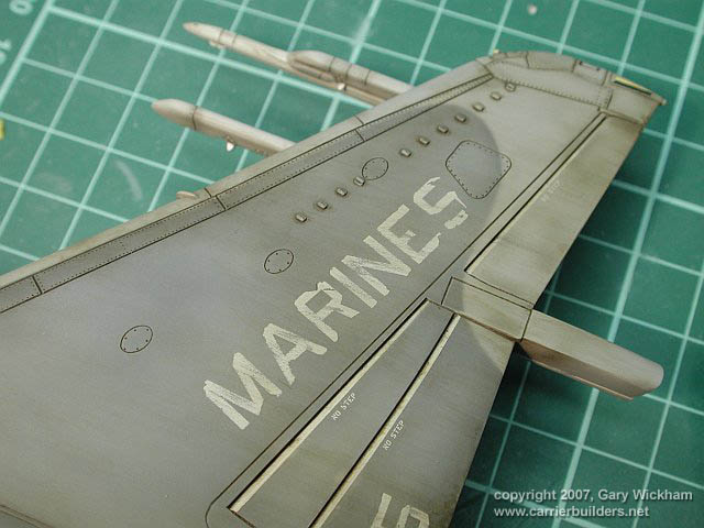
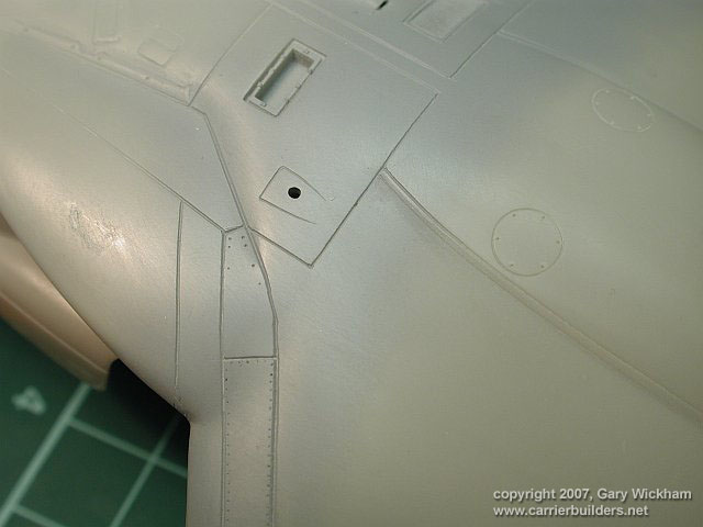
| Figure 1 The wing joins to the fuselage with little drama. The LEX however is the
worst fitting part in the kit so far. This pic shows how the seam between
the LEX and wing needs to be dealt with. |
|
|
 |
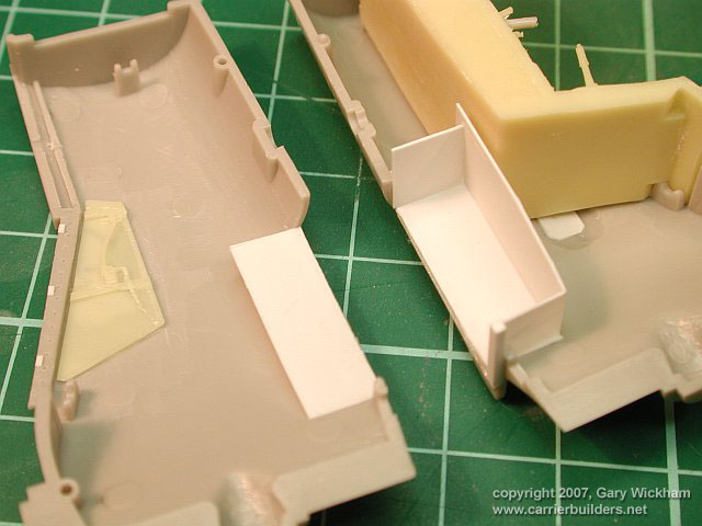
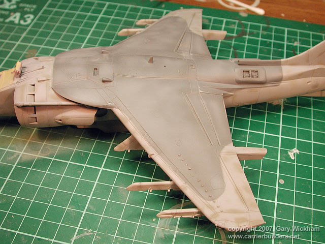
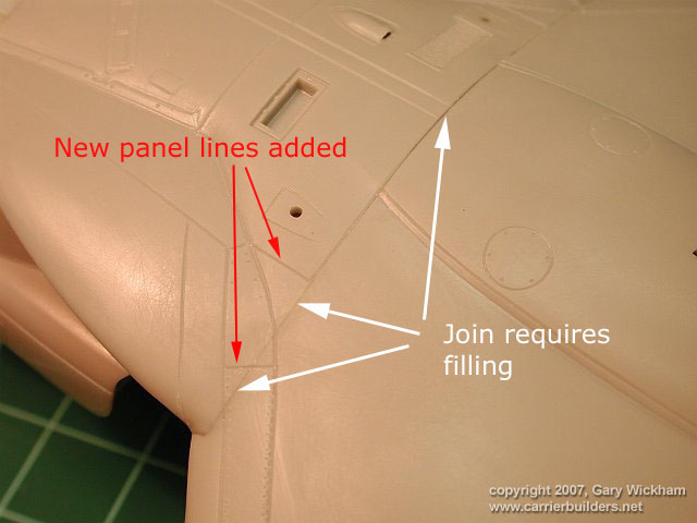
| Figure 2 Once you have filled the outer part of the LEX-Wing join (whilst retaining/rescribing
part of it), you'll need to rescribe the damaged panel lines (and rivets).
You can also then add in the missing panel lines (see red arrows in Figure
1). |
|
|
 |
| Figure 3 A similar story on the starboard LEX to Wing join.. |
|
|
 |
| Figure 4 The finished join after a coat of Alclad Primer. |
|
|
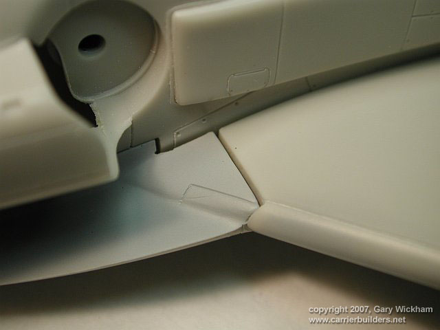 |
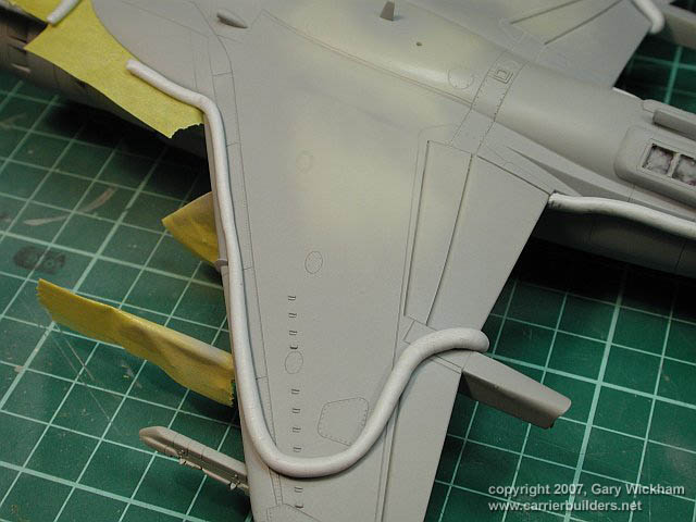
| Figure 5 If you thought all the nasty business with the Wing to LEX join was on
top. think again. The worst gaps are underneath (which is in some ways
a blessing as it mostly hidden). Here you see the gap as it comes from
Hasegawa. Its not obvious from this angle but the is a large step between
the LEX and Wing (as well as the gap) !!!!. |
|
|
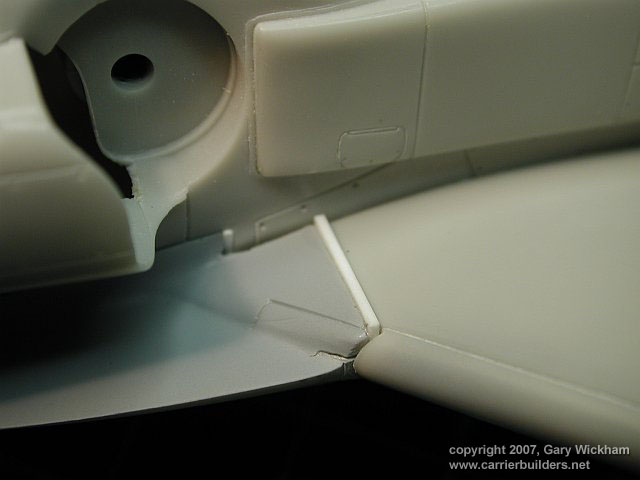 |
| Figure 6 Trusty 10" plastic card comes to the rescue. To fix the step between
the two parts I used brass rod to spread the LEX top and bottom (you can
see a small stress fracture on the LEX due to this). |
|
|
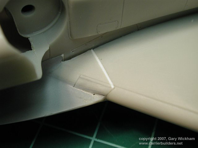 |
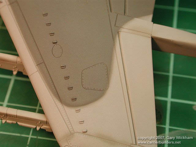
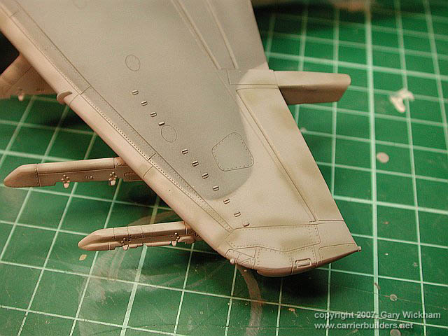
| Figure 7 The gap has been filled and sanded smooth. As the panelline did not line
up (yet another problem), I filled the incorrect one (you can still see
it below the new one) and the scribed a line which was a continuation of
the panelline on the wing leading edge. Note also the fairly large gap
between the wing and fuselage. |
|
|
 |
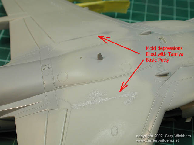
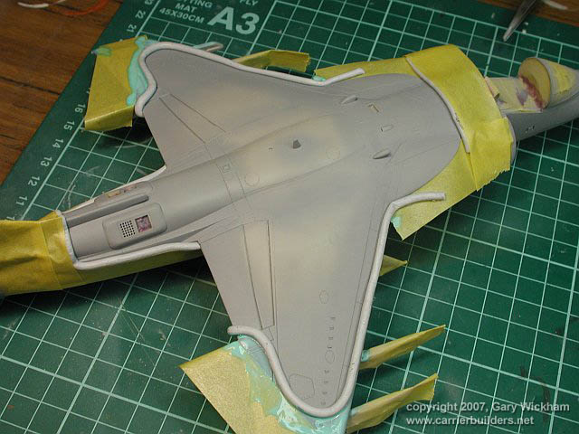
| Figure 9 The finished job. The fuselage to wing gap has been filled with Milliput
and the LEX to wing gap is no longer evident. Finally the panel lines look
they should. |
|
|
 |
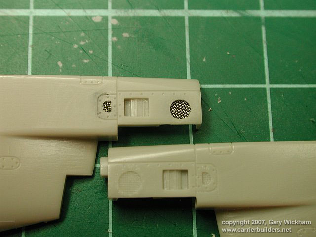
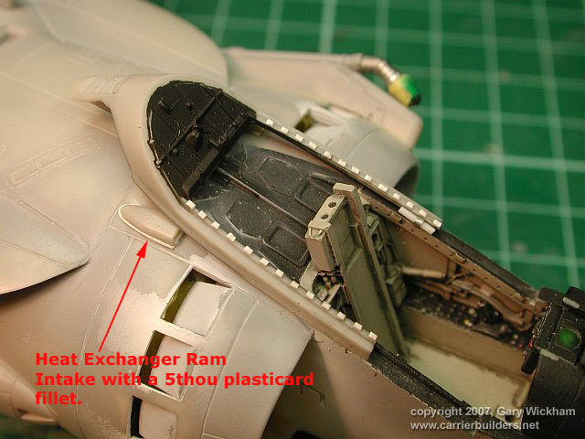
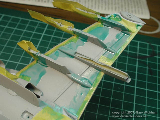
| Figure 10 Here is the back end of the LEX section. You can see the spreaders I used
to try and minimise the step between this part and the wing section. Also
note the white plastic card "gap fillers". |
|
|
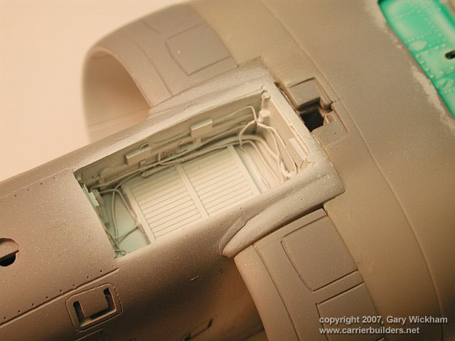
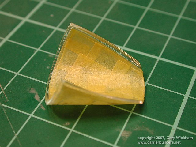 |
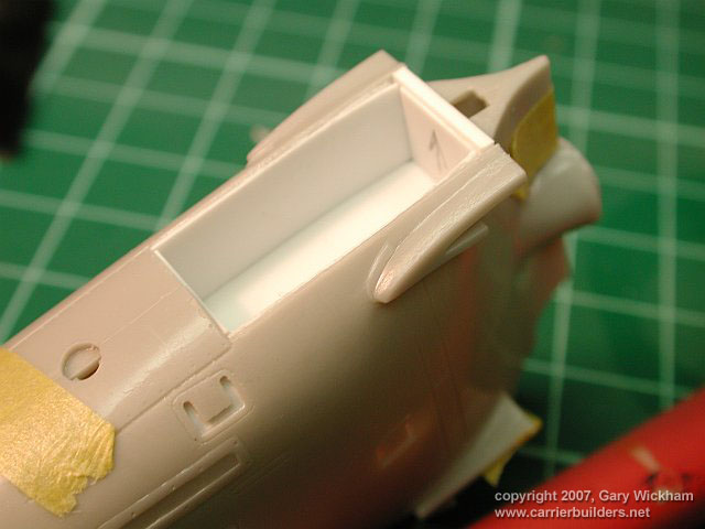
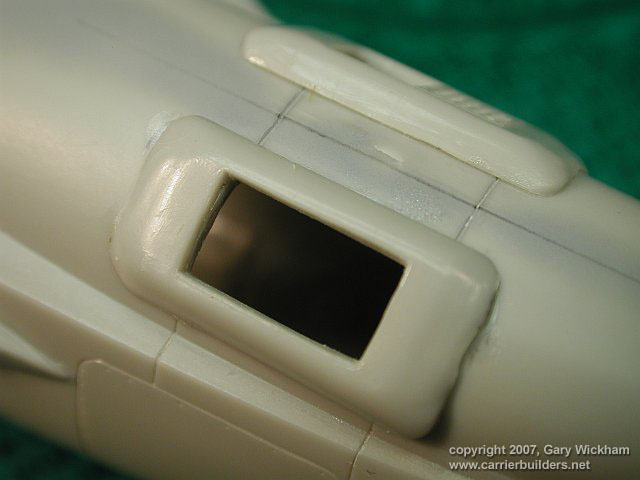
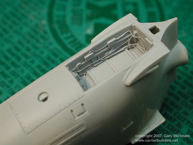
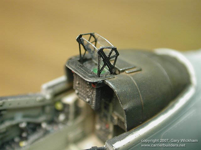
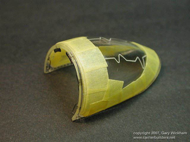
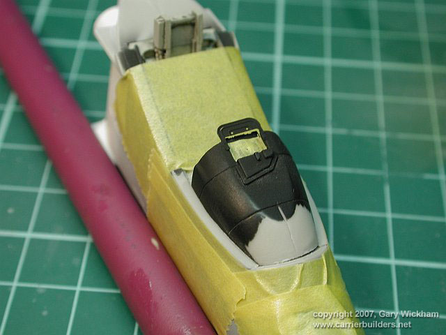
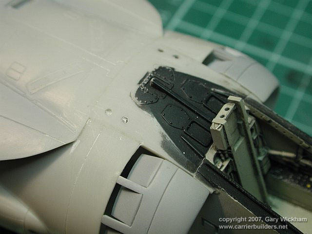
| Figure 11 The interior of the windscreen has been masked to allow painting of the
frame interior. |
|
|
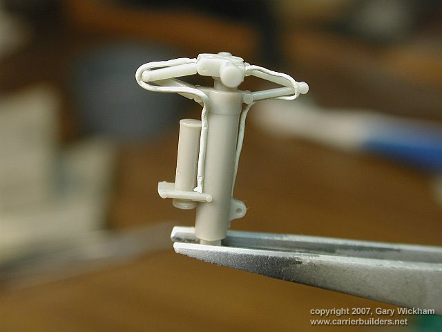 |
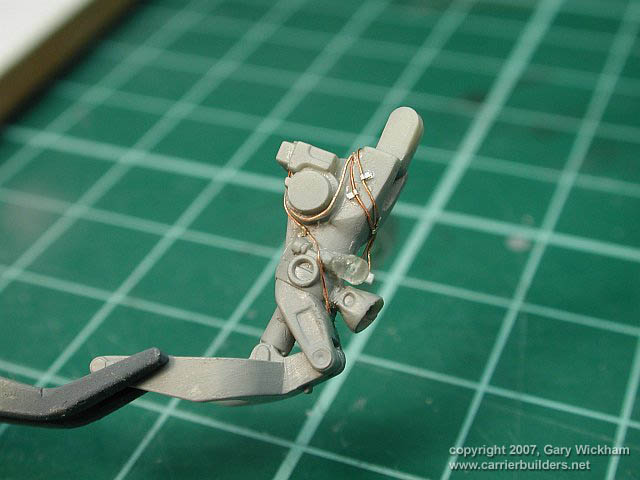
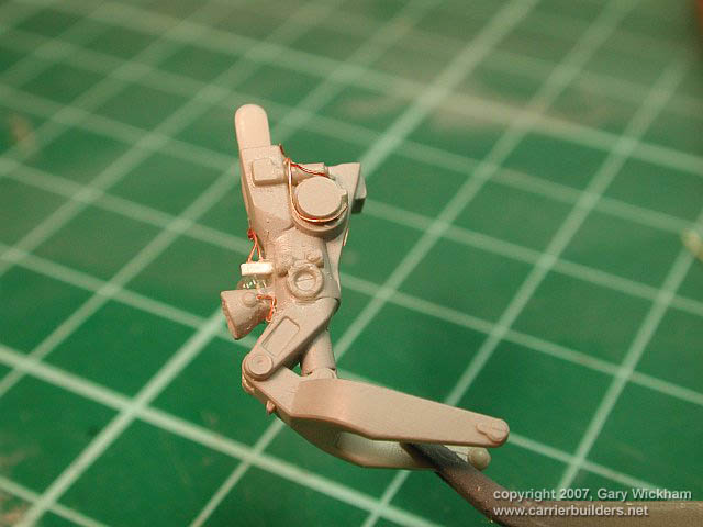
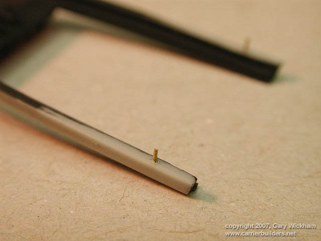
| Figure 12 The main landing gear has been detailed with Milliput brake lines. This
is the first time I've used this method. The jury is still out on this
one. |
|
|
 |
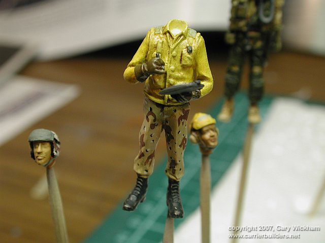
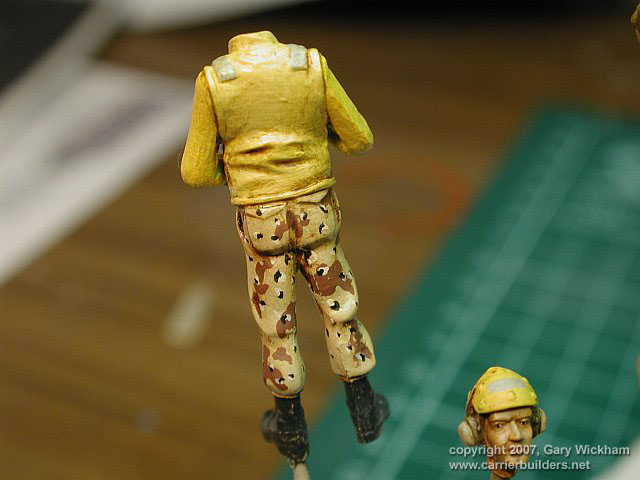
| Figure 13 Ok, now if I hear anyone laughing, you're in for it. Some more to be done
on these guys. This chap is from Verlinden. |
|
|
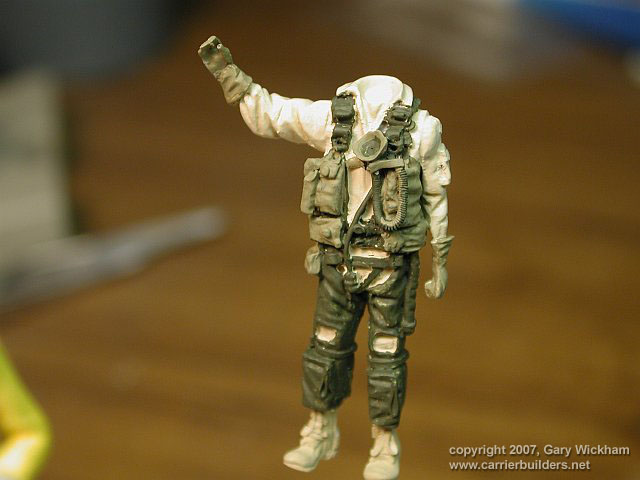 |
| Figure 14 The pilot is from CMK. As the model will be as operated in OIF, I am painting
the flight suit and boots in standard desert kit. |
|
|
 |
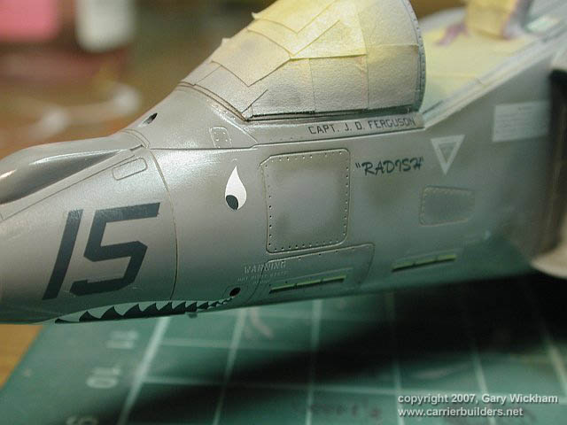
| Figure 15 The windscreen had some noticable fit problems at the front so I fixed
this by thinning down the console. This of course destroyd the paint so
I have masked the area in preparation for a touch up. |
|
|
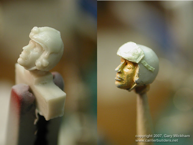 |
| Figure 16 The CMK US Navy pilot figures come with the older helmet type. During
OIF the AV-8B pilots wore the newer lightweight helmets. Here I have removed
the old visor mouting and replaced it with a Milliput lightweight visor. |
|
|
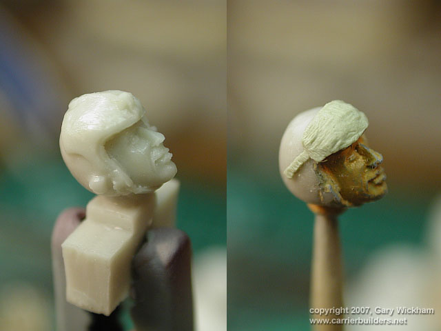 |
| Figure 17 The same guy from the other side. |
|
|
 |
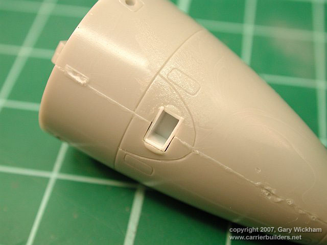
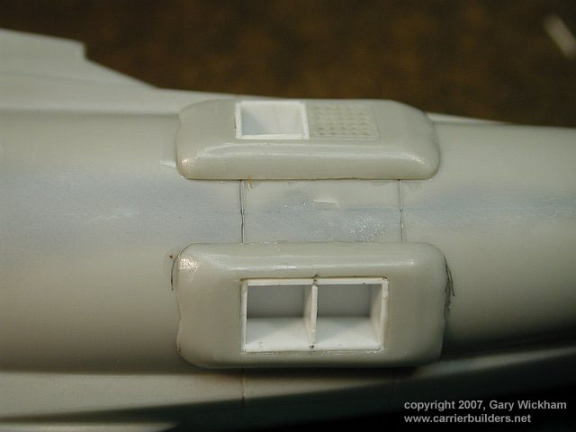
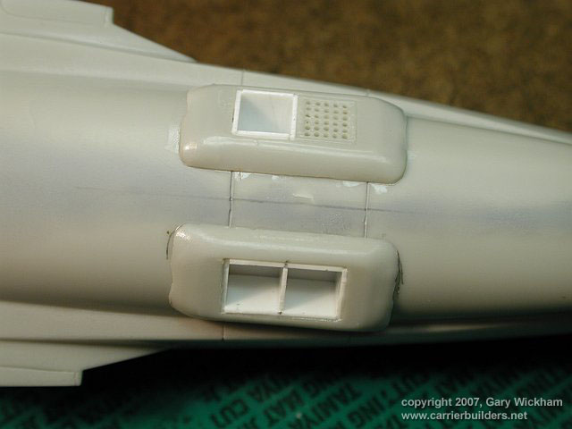
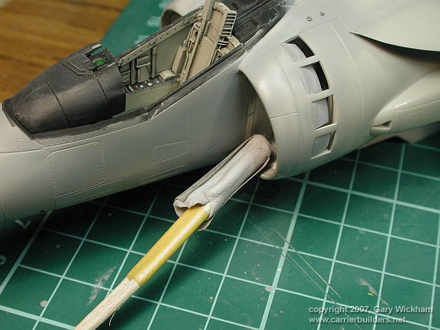
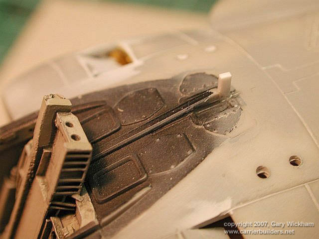
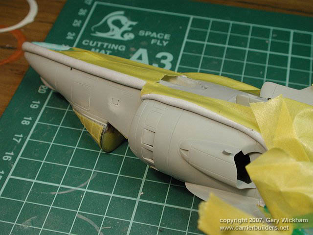
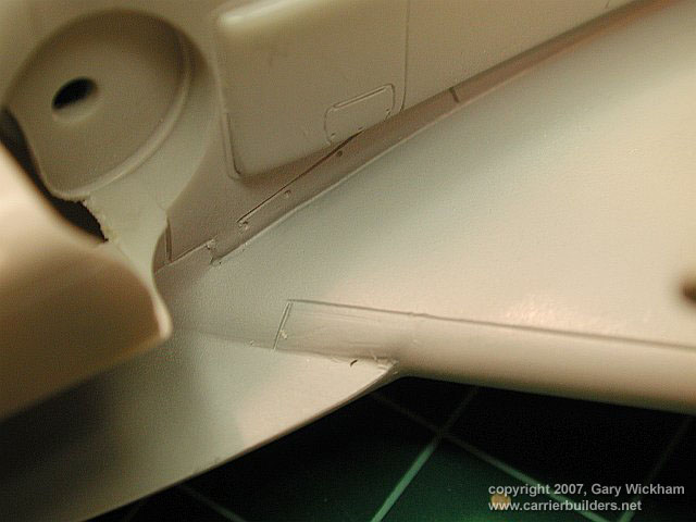
| Figure 18 and you thought that once you fixed the wing to LEX join it was all downhill.
Well sorry but the joint between the front of the LEX and the forward fuselage
is also a shocker. The join between the fuselage and the intakes is also
not the best. |
|
|
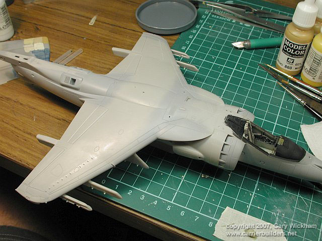 |
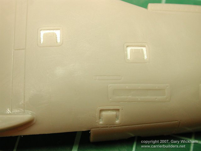
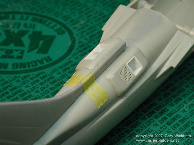
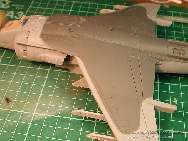
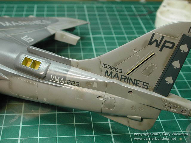
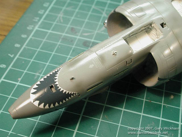
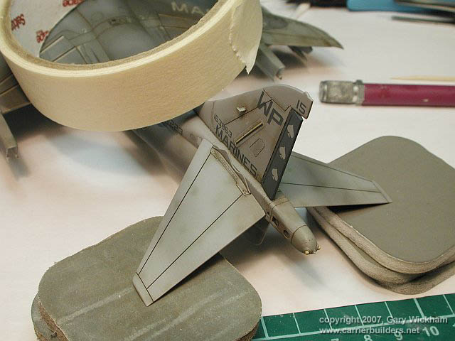
| Figure 19 Starting to finally look like a Harrier. |
|
|
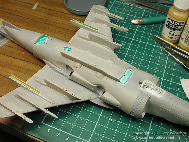 |
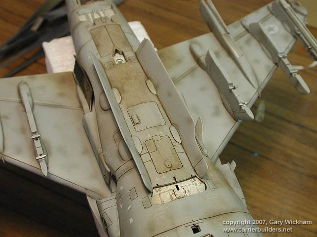
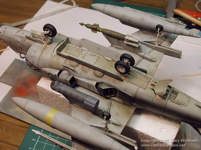
| Figure 20 Pylons are on, wheel wells are masked (with Mr Masking Sol, again the
first time I have used this product). |
|
|
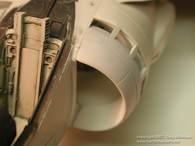 |
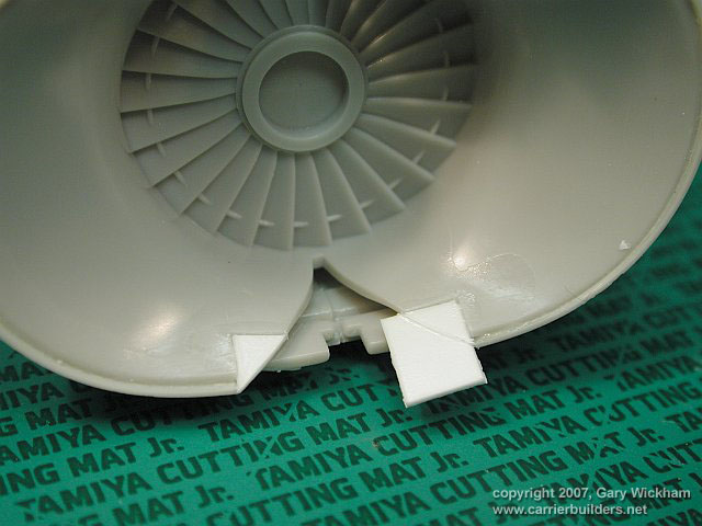
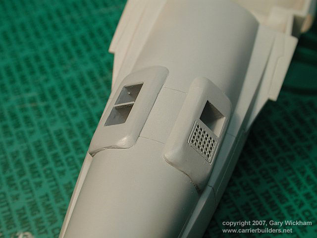
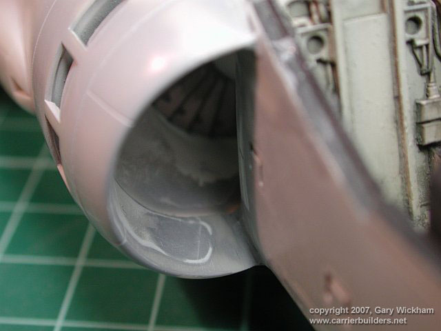
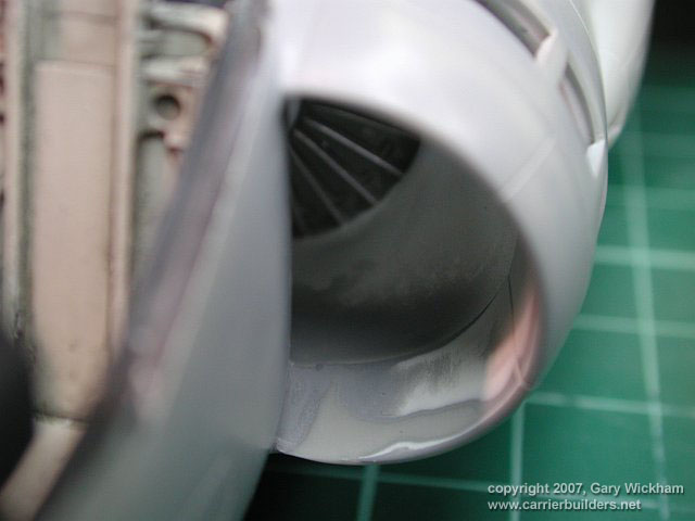
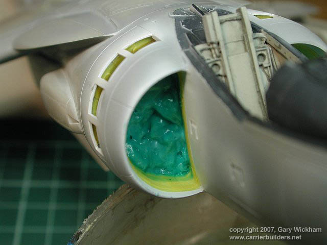
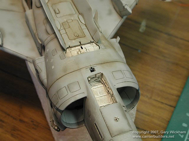
| Figure 21 Some pretty nasty gaps in and around the intake lip as well. |
|
|
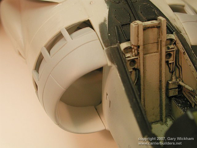 |
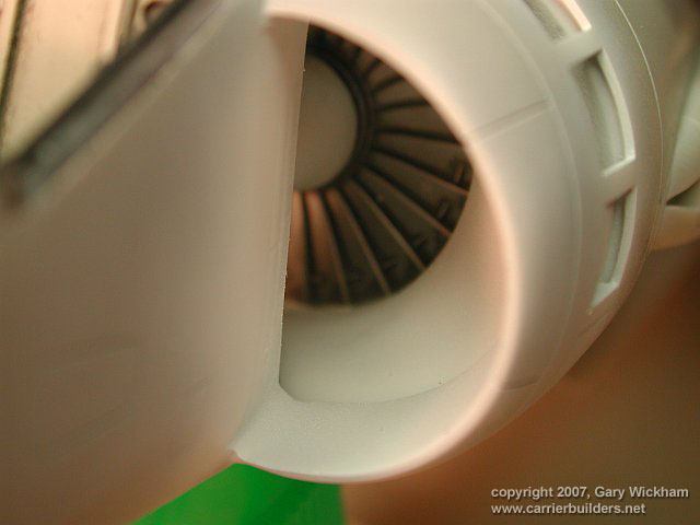
| Figure 22 Notice the nasty step at the bottom of the intake lip. This will not be
easy to sand !!. |
|
|
 |
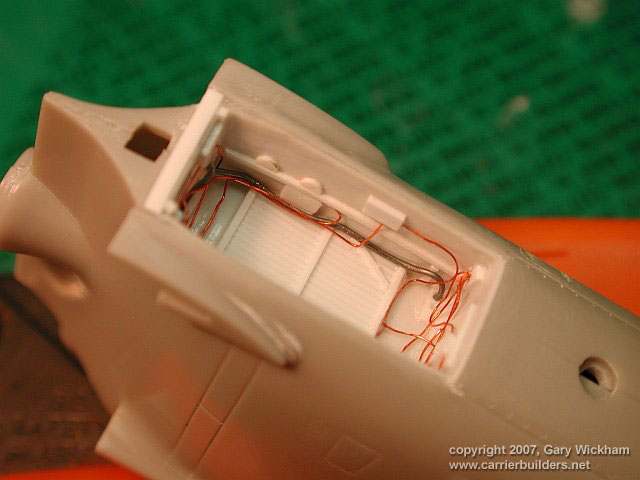
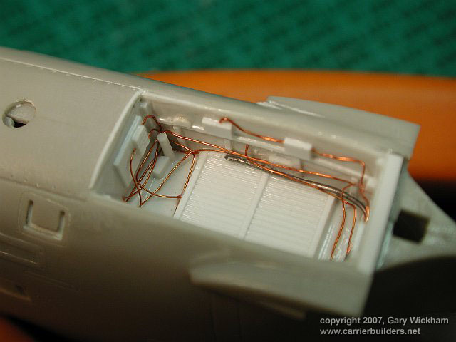
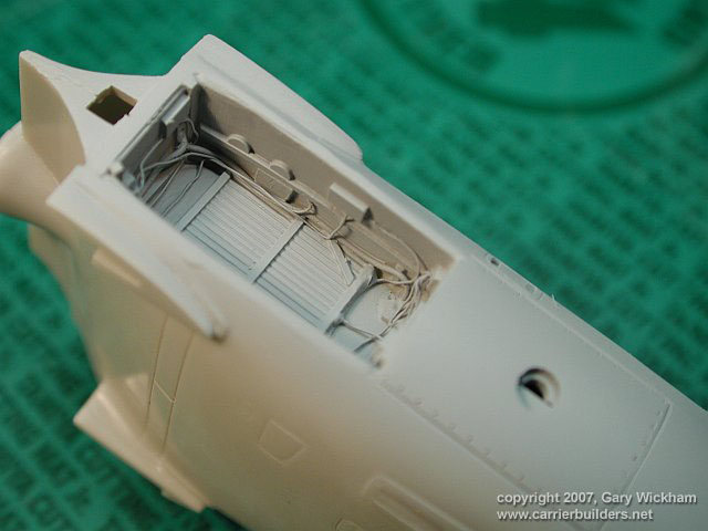
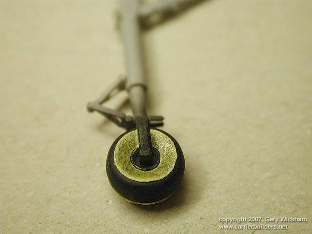
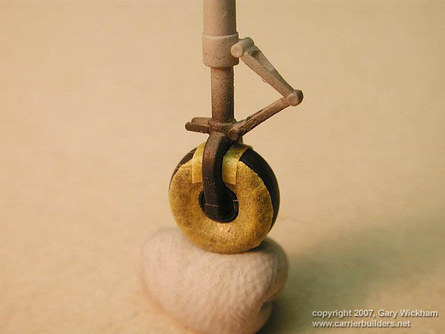
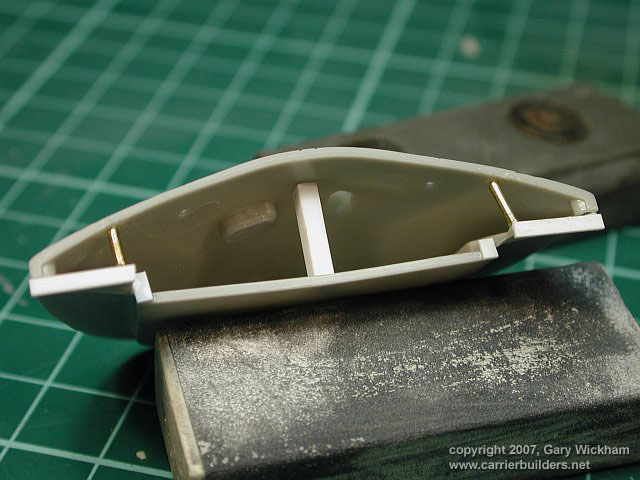
| Figure 23 The scratchbuilt nose wheel well gets a coat of white. |
|
|
|