AircraftProfilePrints.com - Museum Quality Custom Airctaft Profile Prints
|
This model is awarded by Editor's Choice - Excellence Award!
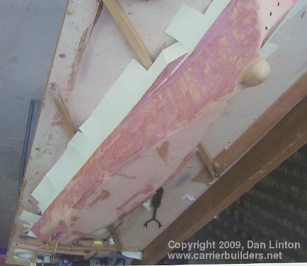
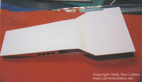
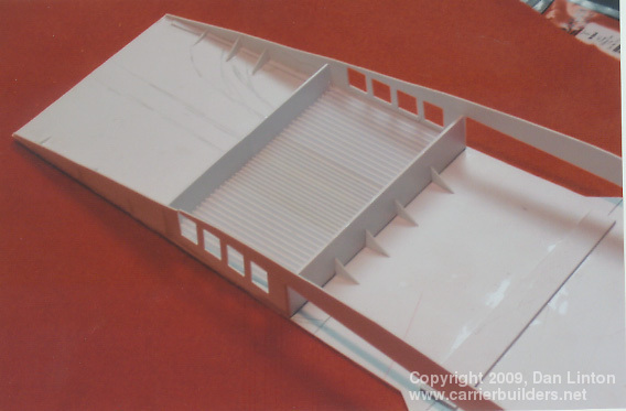
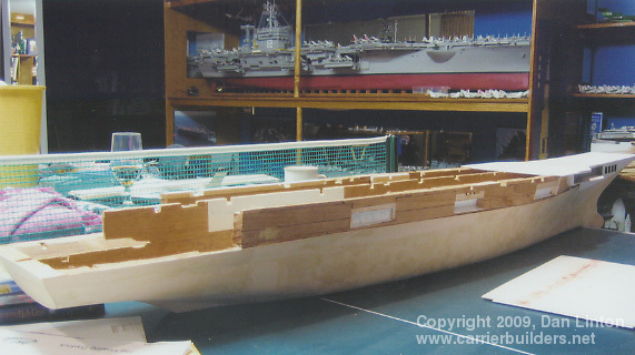
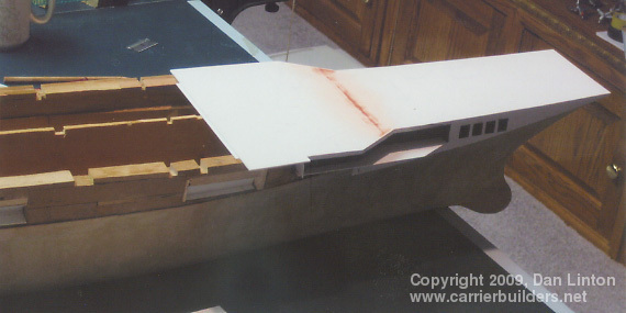
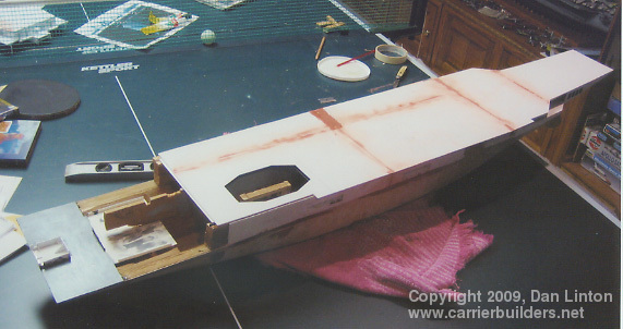
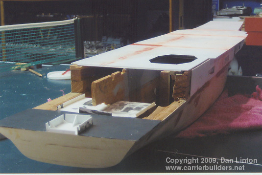
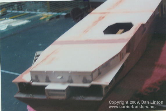
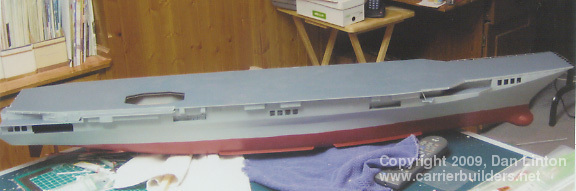
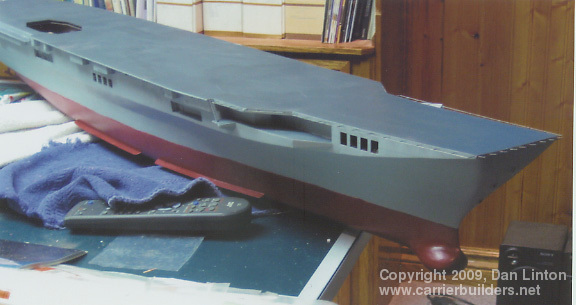
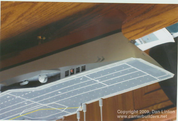
The hull, whose contours I guessed at, is pine that is then sheathed in 1/32" basswood. The sonar dome is carved from maple, a hardwood. The first two pictures show the forward portion of the flight deck: before it could be glued on, a section of the 01 or first deck had to be detailed (where the anchor winches are found) as this area can be seen through openings in the side of the hull. The third picture shows the hull with the first of five flight deck sections added to it. In the middle of the hull is a piece that provides the contour of the flight deck and the white piece of styrene facing you will later be painted as a portion of it will be visible when the partially-lowered rear elevator is installed. Note also the coffee cup and wine glass, tools as necessary as razors and paint brushes. Unexplainably, there is no beer mug in evidence even though much beer was consumed in the making of the Garibaldi. Finally, still with the third picture, in the background will be seen the 1:144 Nimitz in its display area. The next picture shows the centre hull piece and the forward flight deck. The red area, where the two pieces of styrene meet, is created by Bondo, an automotive body filler which is excellent and sands very nicely. The next picture, fifth in the sequence, shows two more pieces of the flight deck attached and at the stern the rear deck has its preliminary coat of deck grey. Inside the elevator well is the support that the elevator will rest on. These styrene flight deck sections are glued onto the wooden hull using Five-Minute Two Part Epoxy Resin which comes in two tubes, one for the resin and one for the hardener. A white plastic lid with a red stir-stick is seen in the upper right of this fifth picture: here resin and hardener are mixed in equal proportions. When doing this I wear thin plastic gloves (the disposable kind a nurse would use) because if I get this glue on my hands, and later touch near my eyes, I get a severe reaction: my eye swells up, crust forms on my eyelids, and ..... never mind, its unpleasant and I need to take precautions. The next picture shows the same progress as the previous one, only from a different angle. The following picture shows the final portion of the flight deck glued in place. The final two pictures in this sequence are the result of my being impatient: I wanted to see what the ship would look like with the superstructure and air wing in place.
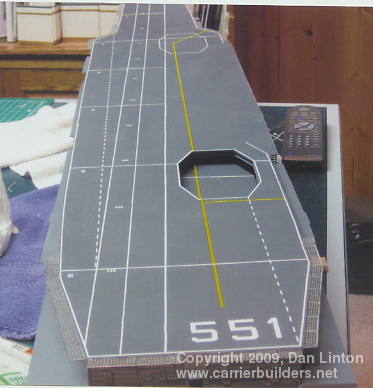
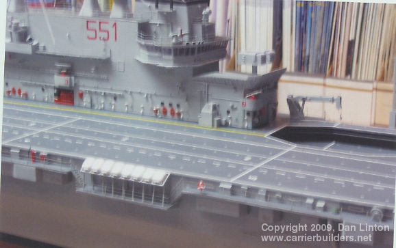
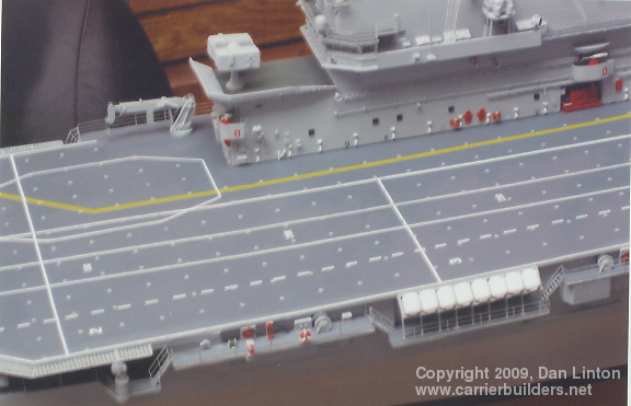
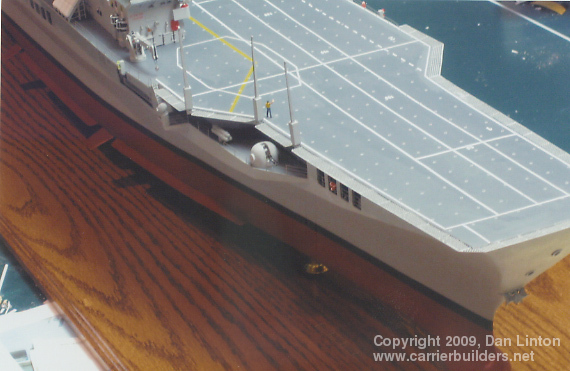
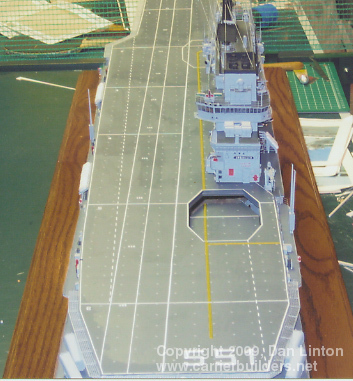
The main picture for Part 2 of this article (look up) shows the hull in my garage ready for painting. Rudder, shafts, and bilge keels have been installed. The white pieces are 'sticky notes' -- they do less damage than regular masking tape --- and I am ready for some spray painting. Note the extensive use of Bondo to try to smooth the hull, particularly at the area where the sponsons meet the hull. Because the weather was quite cool for this part of the world (southern Ontario, Canada) in April and May of 2007, very few days were available for spray painting in my garage. With little time available and working to a deadline, I didn't stop for photographs. That is why the first picture below this paragraph shows the ship fully painted. The beginning of the netting around the forward flight deck is seen in the second photo and the third shows the complete decaling of the flight deck. Interestingly, for a European ship, the small white numbers that you see are in feet, not metres. Just to the right of helicopter landing area '6' is the number '500' representing 500 feet from the bow. Not seen in this picture is the boot topping (the black area between the red of the bottom hull and the grey of the upper hull) which I created using decals, giving a sharper line than I could ever achieve with an air brush.
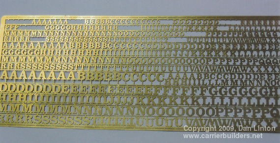
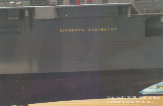
At the stern of American Warships, the name is painted black but many European navies, particularly the French and the Italians, have the ship's name on both port and starboard sides towards the stern. For the Garibaldi, the name is just forward of the large captain's boat at the stern (this can be seen in the Walk-Around on this website). Each letter is actually a piece of metal welded onto the hull. The replicate this, I ordered a brass PE (photo-etch) fret from Loyalhanna Dockyard. This is seen in the first picture below. Notice that many are missing --- they are the one's I used for this model. This was the most maddening part of the build. Superglue is necessary to bond metal to the plastic of the upper hull. There are 17 letters in 'Giuseppe Garibaldi', done on each side, and in a straight line. If any single letter was even the tiniest bit too high, or too low, or not perfectly straight up and down and level, it would be very, very obvious to the eye. I came close to tears of frustration in doing this: more than a dozen letters had to be sliced off the hull and be reset. The second picture shows the results.
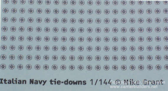
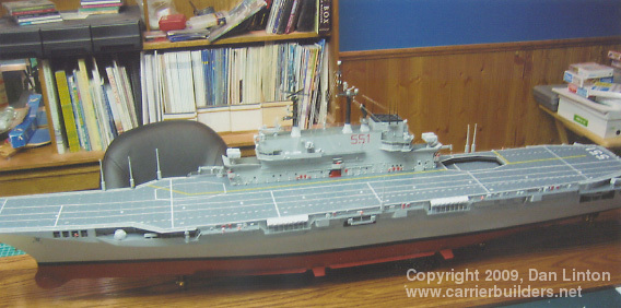
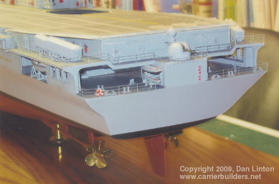
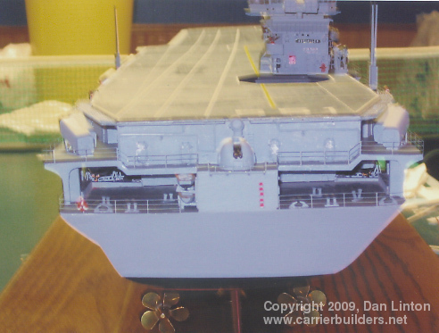
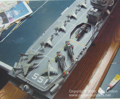
The next picture is self-explanatory. Mike Grant, of Mike Grant decals, modified the artwork he produced for me years ago when he created tie-down decals for a 1:144 Nimitz. USN tie-downs have five projections that chains are tied to but the Marina Militaria Italiana only uses four, and Mike produced them for me. The can just be seen on the deck in the next picture. Here the ship is complete and is installed on brass finials (3) on an oak display board. To the left on this board is a brass plaque indicating the ship, scale, and builder. Note the two cranes (forward and aft of the superstructure) and the six large radio antennas. The next picture shows the completed stern. When I began the build I was confident that the Garibaldi had 4-bladed propellors -- not until four months before the deadline did I learn that it had 5-bladed propellors! I managed to find props of the correct size and order them: they were delivered and installed with a month to spare. The next five pictures provide a tour around the finished model before the air wing was put in place. The second to last picture shows the stern again and the final picture shows the partially-lowered elevator.
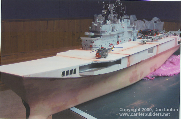
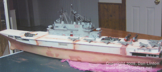
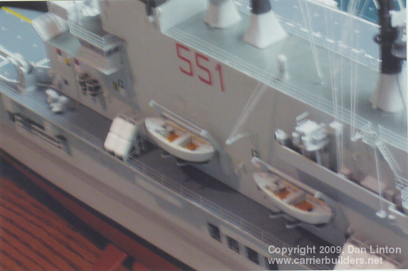
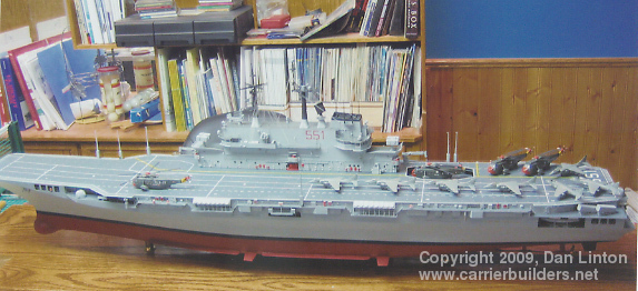
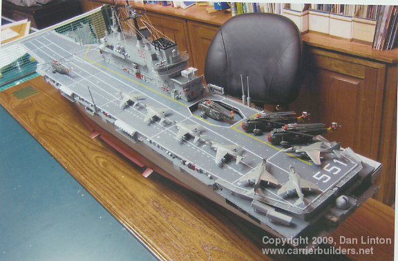
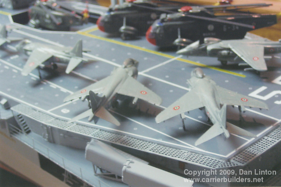
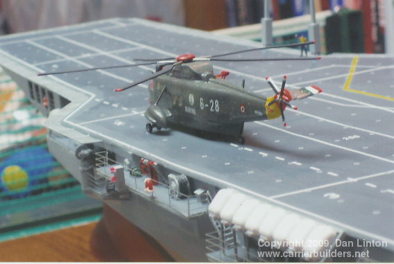
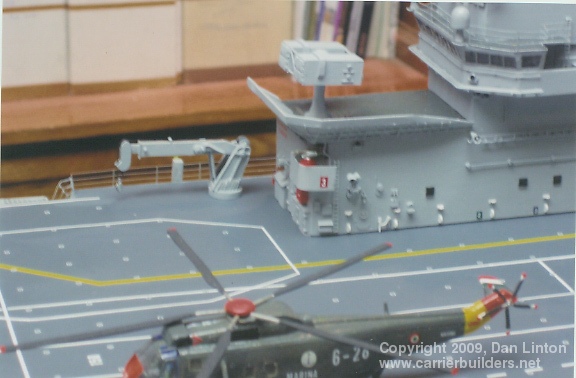
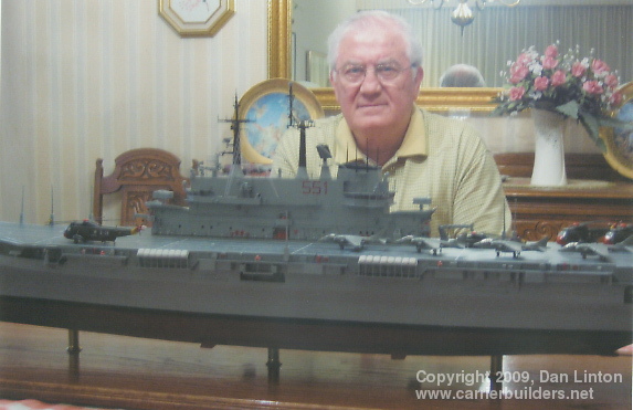
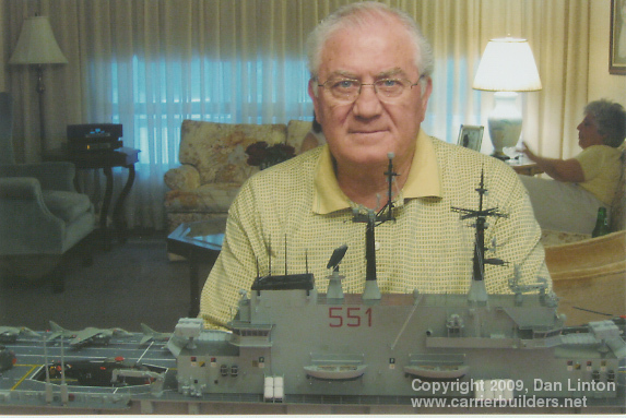
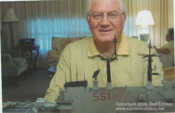
The first picture shows the model ready for delivery and the second picture is a good view showing the aircraft in place on the model. The particular positioning of the various aircraft is based on actual pictures with one exception -- I wanted the white pennant number '551' on the flight deck to be visible. The next two pictures show the rear flight deck while the fifth picture of this sequence isolates the forward Sea King helicopter. This is followed by a picture that focuses on the forward crane. The ship's two cranes took more than a full day to produce and were the last pieces completed. And the frowning man in the last two pictures is my uncle, Michael Montanaro. More than 15 years ago I made and gave him a 1:192 Vittorio Veneto (C550), a modern missile cruiser. It was 34" (86cm) in length and of course much narrower than the Garibaldi. Despite warnings, he and my aunt were expecting something along the size of the earlier model but when my wife Susie and I carried the Garibaldi into their house on June 3, 2007, the first shocked reaction was "where are we going to put this?" The display board for the Garibaldi is 60" x 15" (152cm x 38cm) and the model sits 18" (45cm) high. They found an area in their house for the model but then moved to a condominium: to protect the model is was brought back to my house and then 're-delivered' in November, 2008.
And the lessons learned from this build? There are two. First: never again build a large-scale model without having accurate hull cross-sections. Correcting errors, or what seems to be an error to your eyes, simply takes up too much time and energy. And second: never again build to a deadline, even a self-imposed deadline. As the days rolled on towards the deadline, the build became less and less a relaxing hobby and more and more of a job I had to report to every day and night. But I'm glad I built it: the picture at the end of this article finally has my uncle with a smile on his face.
Photos and text © 2009 by Dan Linton March 2, 2009 |