AircraftProfilePrints.com - Museum Quality Custom Airctaft Profile Prints
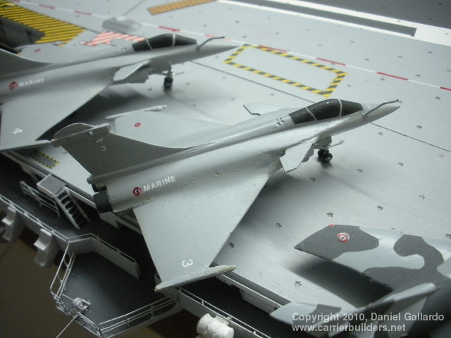
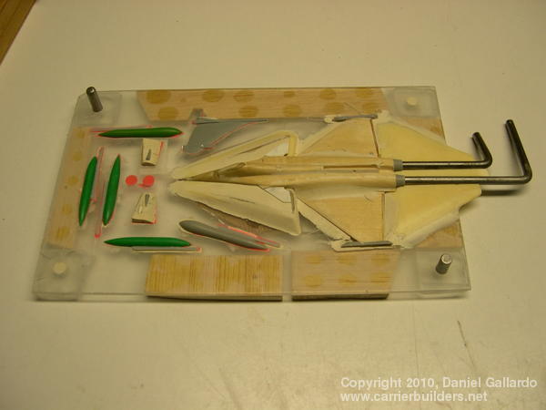
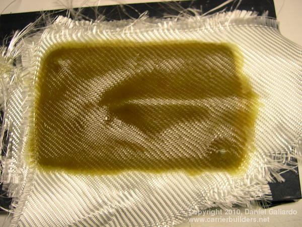
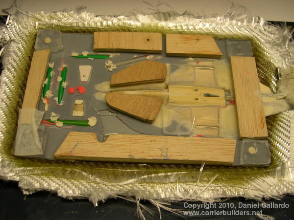
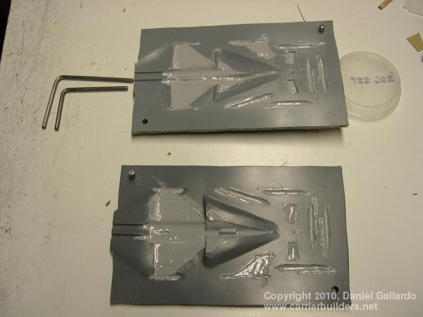
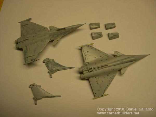
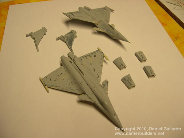
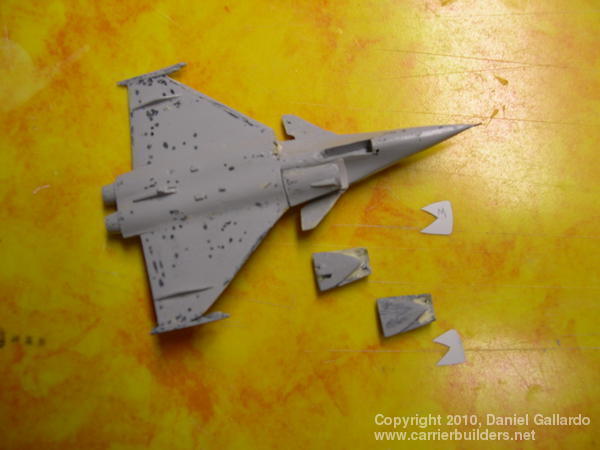
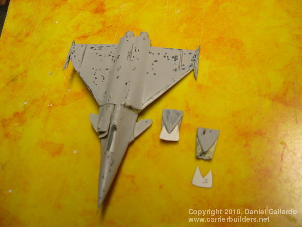
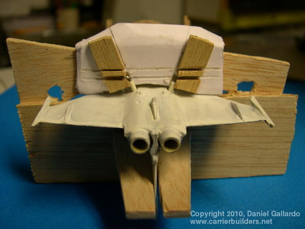
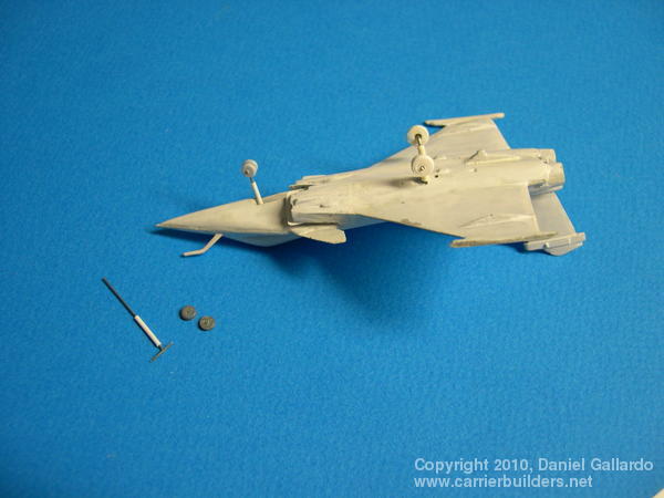
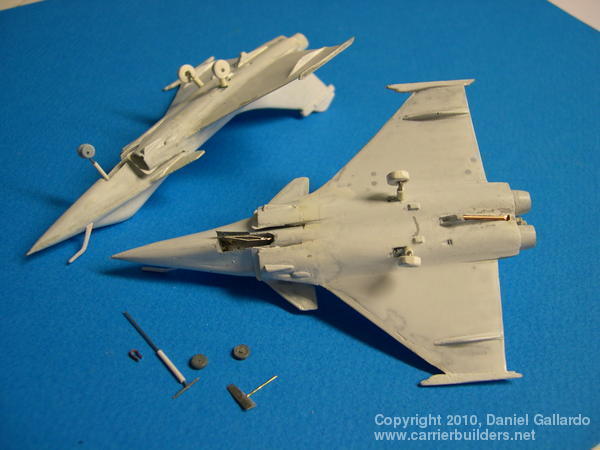
The planned air wing for France’s first nuclear aircraft carrier, Charles de Gaulle, is 40 aircraft. Ultimately, the SEM’s (Super Étendard Modernisé) now used for attack will be replaced by the Rafale: the few machines carried on the first few cruises were dedicated for air defense, but the F3 version now entering service can satisfy both roles, so that only Rafales, Hawkeyes for early warning and air control, and a helicopter or two for plane guard duties will be found on CDG’s flight deck. The CDG is large enough to carry more aircraft but the Rafale does not have folding wings (a cost-cutting measure to keep the marine version from being too different from the plane the air force flies) and additional accommodation for the servicing of extra aircraft would strain both space and consumables. For the model I made, I have a very small air wing – 3 Rafale, 7 SEM, 1 Hawkeye and 1 helicopter. The Hawkeye and the helicopter were made from wood; the Rafales and SEMs come from glass fibre and epoxy resin moulds. Rafale: Making the Mould Picture 1 shows the beginning of the processes for making a Rafale using glass fibre and epoxy resin. The base is a rectangle of plexiglass. The wood used for the wing and fuselage has been sanded and polished several times. The light sand-coloured material is sintofir which hardens nicely and can be shaped (note the separate air intakes and the joint between the wing and fuselage. The same material, a form of modeler’s paste, will also be used later to correct mistakes. Picture 2 shows the epoxy resin poured over the pieces as the first gel coat and Picture 3 shows the glass fibre being added. Ultimately there will be 10 layers of this fibre. Picture 4 shows the bottom part of the mould, the light sand-coloured sintofer being used in a few places here to hold pieces in place. Picture 5 shows the two parts of the mould ready and picture 6 has half the mould ready for a further waxing and polishing. Gel is now put into the two parts of the mould (picture 7) and they are joined together. I have made three so far: picture 8 shows the first two when the moulds were pulled apart and the pieces separated. This is shown from a different angle in picture 9. Picture 10 shows the air intake, and the splitter plate between the fuselage and intake, being glued on. Again, this is seen from a different angle in picture 11. Picture 12 shows all the major pieces glued on and the aircraft are being readied for finishing.
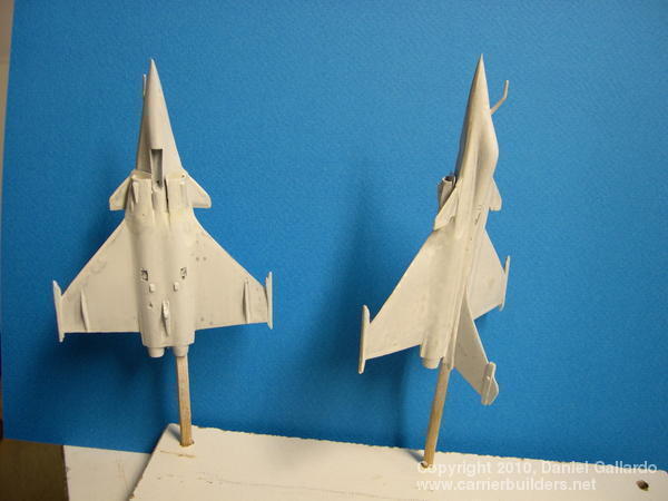
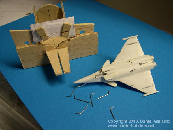
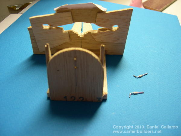
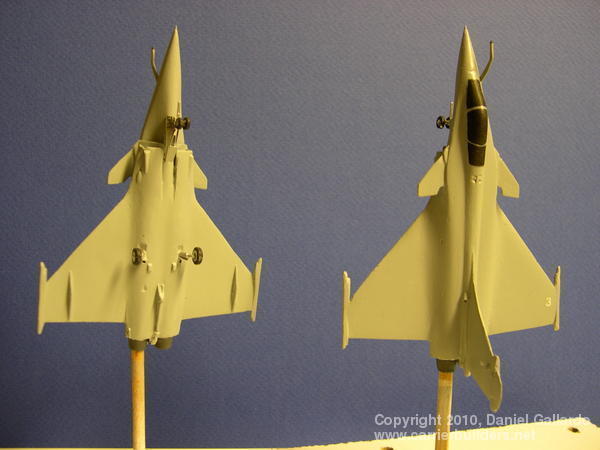
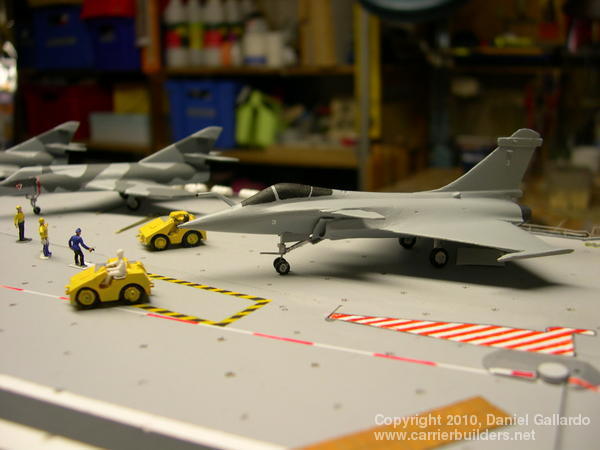
Picture 13 (above) shows two cleaned-up aircraft: they have been given a light primer coat to show up any minor defects. Picture 14 shows the piano wire used for the landing struts and it also shows the jig I made to get the angle correct for gluing in the main landing gear. Pictures 15 and 16 show the jig from another angle and then in use, an aircraft in place and the landing gear being glued. Pictures 17 and 18 show the nose strut, the wheels, and the tail hook being glued into place. Picture 19 begins the painting – notice the number ‘3’ on the wing: it is from a ‘letraset’ (press-on) sheet. Picture 20 shows this aircraft on the deck: its canopy is painted black but as yet there are no other markings on the model except for the white number ‘3’s. Notice also the crew member in the tractor is not painted.
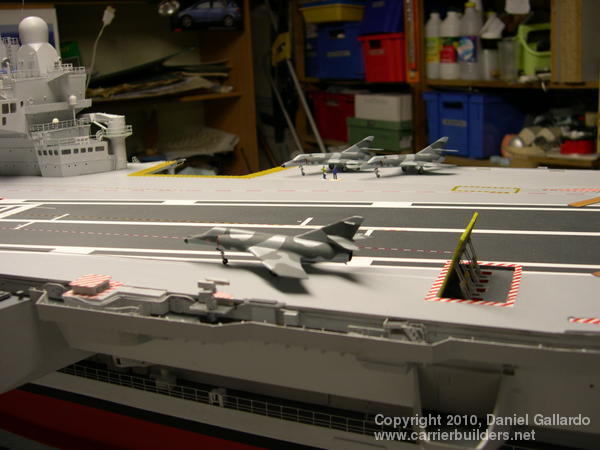
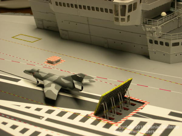
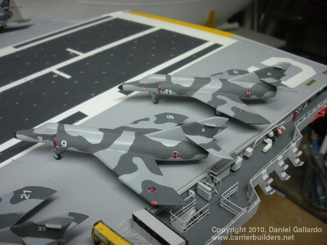
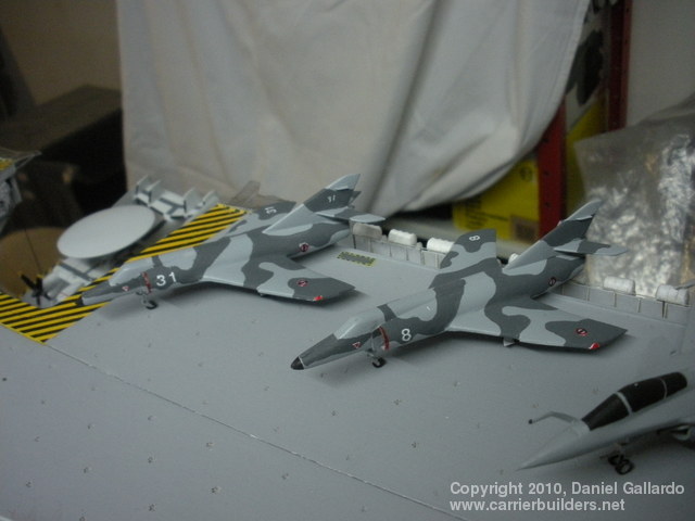
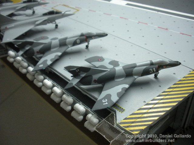
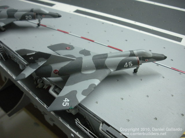
The Étendard (an ‘étendard’ translated into English would be ‘battle standard’ or flag) has been the standard French naval attack aircraft since the 1960’s. The ‘super’ model was created in the late 1970’s and gained fame or notoriety when used by Argentina in successful attacks on British ships using Exocet missiles during the brief Falklands War in 1982. It is at the end of its service life now, and will be fully retired by 2015 (extended from the originally planned 2010). I have seven of these as they were originally produced for my 1:150 radio-controlled model of an earlier carrier operated by the Marine Nationale, the Foch. They were produced by the same method used for the Rafale described above. Picture 21 (above) shows a SEM at the waist catapult of the CDG and another two at the starboard deck edge. Picture 22 below shows the same machine closer-up. Note that I have neglected to paint the canopies on these aircraft. This is a forgivable fault: I suspect most modelers are like me and have more than one project on the go at any time and when this happens, some things are forgotten. The translator of these articles pointed out that the canopies had not been painted: I assured him they would be done – someday. Picture 23 shows that all the details on the SEM have been completed except the painting of the canopy. Picture 24 shows another machine, while picture 25 shows two more on the starboard deck edge. The last two pictures, 26 and 27, show these machines from a different angle. Over its long service life, the Super Étendard has been upgraded five times, but virtually every upgrade has involved its electronics and cockpit arrangements: the actual airframe has remained basically untouched which is why I can place these aircraft on either the Foch or the CDG and still be accurate.
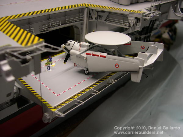
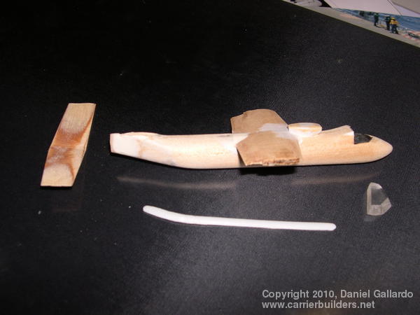
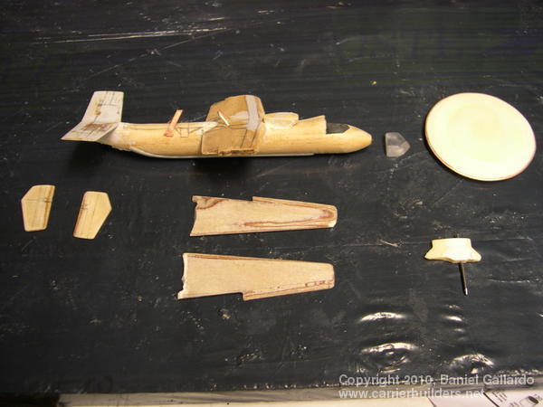
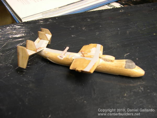
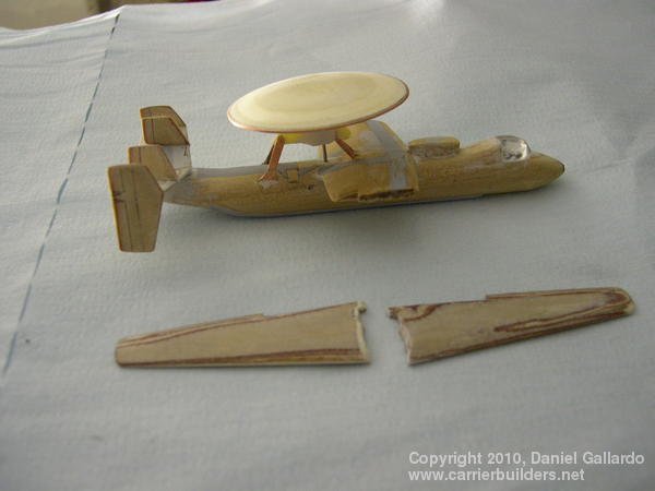
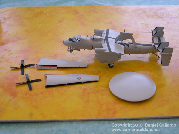
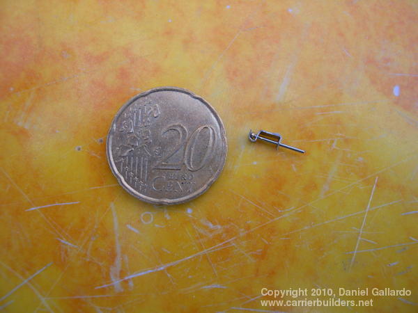
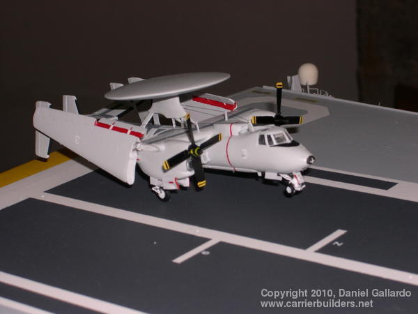
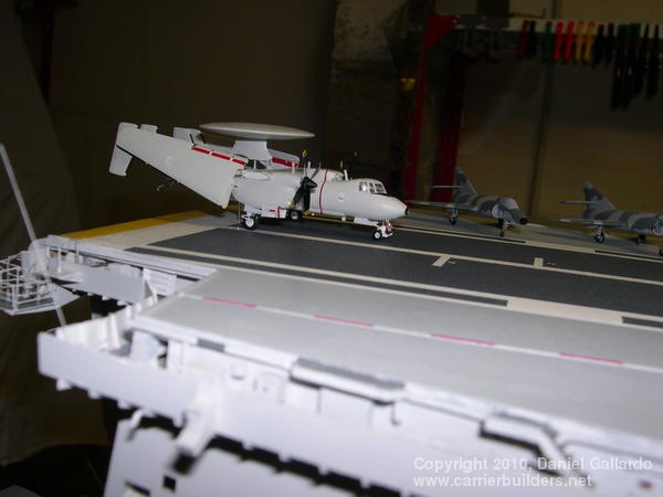
Currently, France has only three of these aircraft, two serving on the CDG at any given time. More would of course be useful but these are very expensive aircraft and more will not be ordered until (or if) France decides to build another aircraft carrier: then one can expect another three to be built for the Marine Nationale. The completed aircraft can be seen in picture 28 (above) but it began as pieces of carved wood (pictures 29, 30, 31, and 32). I bought a 1:72 plastic kit and used its plans as the basis for my 1:150 scale. Note the piece of plexiglass for the canopy area and in picture 32, where the two pieces that made up the rotating radome meet at the edges, a very thin sheet of copper was used and pushed and tapped into place to make the edge smooth and crisp. Picture 33 shows the major pieces now painted: the landing gear and tail hook were fashioned from copper wire. The nacelles are hollow and into them went the ‘motors’: (picture 34) more accurately, spinning devices that the propellers and propeller hub attached to. Picture 35 shows the fully-assembled aircraft but not that it is a tail-sitter: weight had to be added to get the Hawkeye down on its nose-wheel. (picture 36) Note that while the flaps are down and the number applied, I still have not made the roundels. Picture 37 shows the aircraft in position for an experiment I tried: if you remember the little ‘motors’ from picture 34, the whole point was to have the props spin like those of a windmill and if you go to http://www.dailymotion.com/video/xefkam_point-fixe-des-moteurs-d-une-maquet_creation you will see the Hawkeye’s propellers spinning madly. The wind in this case was provided by a hair dryer that was blowing off screen. I want to build another Hawkeye, the modernized version that has eight propeller blades on each hub, and this one will have actual motors buried in the nacelles. The motors will come from those found in cell phones, only 5mm in diameter and 8mm long, drawing only 1.2 volts.
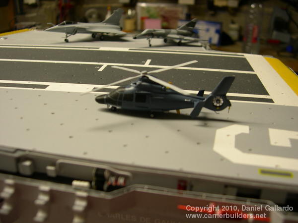
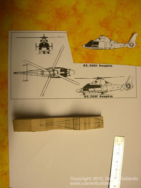
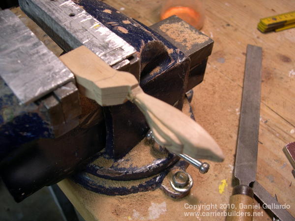
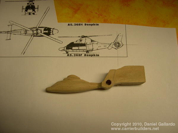
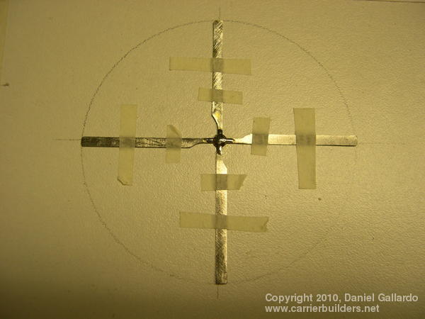
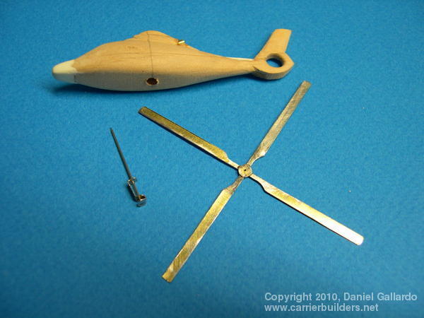
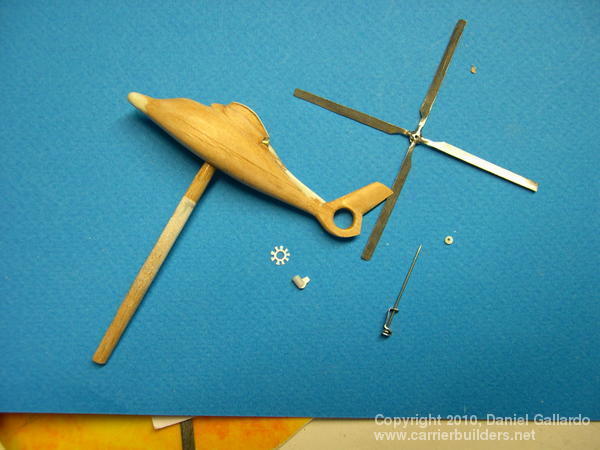
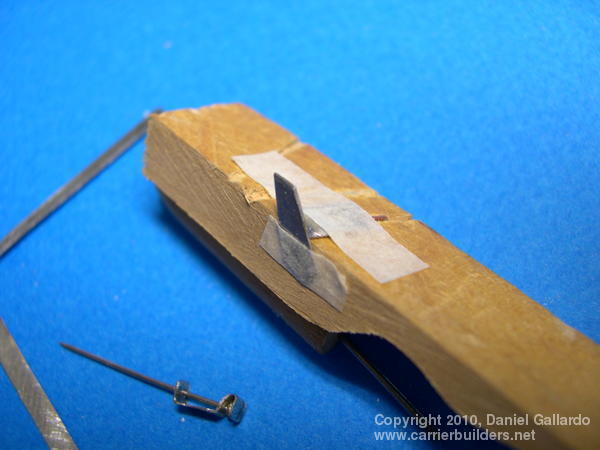
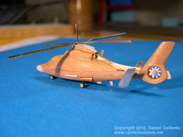
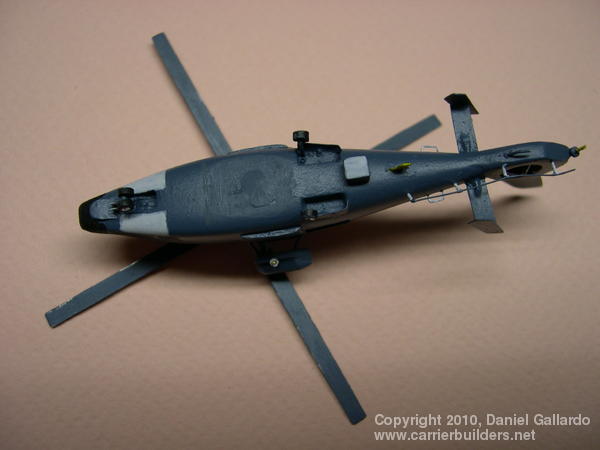
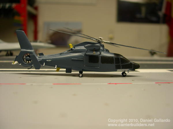
The Dauphin helicopter seen above in picture 38 is used for plane guard duty on the CDG. Like the Hawkeye it is made from wood, the pattern and the block cut-out is seen in pictures 39 and 40 below. Picture 41 shows why the area around the fenestron (the term for the circle of metal that surrounds the rear propeller) was not cut out: it made the sanding and smoothing of the majority of the fuselage so much easier. The hole was then drilled out where the small propeller will be placed (picture 42) and then work was begun on the main propeller blades (picture 43). Another hole was drilled through the fuselage to accept the propeller and its mounting piece (picture 44). Plastic was used for the small helicopter blades and other parts of the fuselage (picture 45) and the fins of copper were soldered to their supports (picture 46). Picture 47 shows all the major parts glued on and the angle of picture 48 allows the hoist mechanism on the helicopter’s right hand side to be seen. The helicopter was painted a very dark grey (picture 49) and picture 50 shows the windows done in black. I still have to put a few markings on this helicopter to complete it. The main propeller blades on this aircraft also rotate: view http://www.dailymotion.com/video/xefzc9_helicoptere-au-1-50eme-sur-une-maqu_creation Will I produce more aircraft for this ship? I have that intention but other projects often divert my attention so only time will tell if my CDG air wing will grow. Next: On the water and on display.
Photos and text © 2010 by Daniel Gallardo August 14, 2010 |