AircraftProfilePrints.com - Museum Quality Custom Airctaft Profile Prints
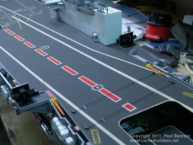
Part 2 mentioned the basic construction of the flight deck and why I made it immediately after the hull. This covers the finishing off of the deck and a little more detail on how I did it. What shape the flight deck should take and how it is constructed appears to be a highly emotive subject among those who make model carriers and in the end the choice is that of the person doing the ‘making’ I will only describe what I do and why I, personally, do it that way. My biggest problem is transportation and with the Truman I HAD to build in two halves. With Hermes I did not have this problem, the finished boat fitting nicely in the back of the car in one piece - result - a one piece flight deck. Why one piece and totally removable? One piece is more authentic, the only ‘holes’ you should see in a flight deck are the aircraft lifts, bomb lifts, jet blast deflectors (JBD’s) launch howdahs and in the case of US Carriers the pop up service centres. Staying with this principle I think it is impossible to fix the flight deck down and still be able to get at all the electrical equipment many of us put inside our hulls. I have seen panels cut in surfaces that accurately that the line is barely visible but this is certainly way beyond my abilities - even if I wanted to go down this road. The first stage of completion was to finish the lining which was done with a combination of masking off and painting and some vehicle pin striping tape. Catapult tracks were done in the same way after making and inserting the centralizing rollers for each track.( One thing the US Navy has never taken up from the Royal Navy) At various stages the whole deck was sprayed with a matt lacquer which allowed further masking over areas that had already been done once, with a final double coat to finish off.
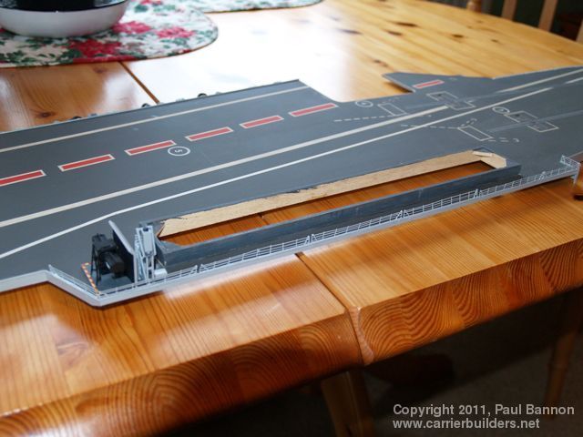
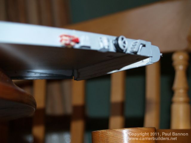
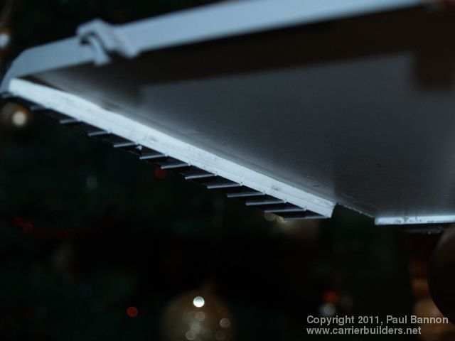
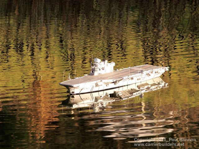
The flight deck was then located by building the bow and stern Round Downs, each of which hooked over the hull. The bow first with the deck then being put in place and the underside of the stern round Down glued in place. The result was a good fit using the flexibility of the plastic to locate the bow and then lower the remainder in place and clicking the stern down. An edging strip was then made from thin flat Styrene sheet topped with Styrene rod. This gave the ‘trip’ rail. In reality this is about nine inches high goes around the whole flight deck and was one reason for so many pipes down the side of the carrier, many were drain pipes from grids on the flight deck to allow for water run off. These strips also provided a mounting surface for the things that populate the cat walks, fuel lines, fuel recuperators, fire hose racks, foam lockers and steps all of which come away with the deck. On the Truman, these small items were fixed to the hull but with Hermes I felt the risk of breakage was worth it to cover the joint between the deck and the hull All the above parts were made in a session of their own and stored for use as required. The fuel lines are not truly accurate and I think will be changed for home made eight spoke wheels in the future. This is another point were what you are building begins to depend on the next stage having been made - in this case the Island. Consequently the basic Island was made to enable me to cut the flight deck and insert a wooden lip which would locate and hold the Island. This lip also helped in stiffening the deck around the Island and help with the deck edge rail that has to go outboard of the Island. This rail should be one piece but with flight deck being flexible I made it in sections - one piece would have sheared - so far it has survived. The only other items to go on the deck were the Crash barrier arms, a small arial and the second Landing Aid. Some of the lining may have to be redone as later pictures would indicate that some colours are wrong but this has yet to be confirmed.
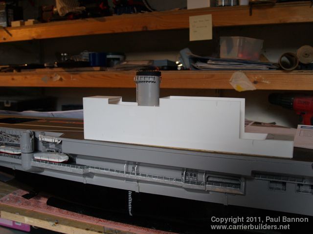
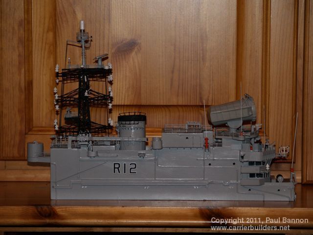
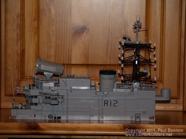
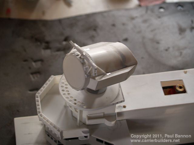
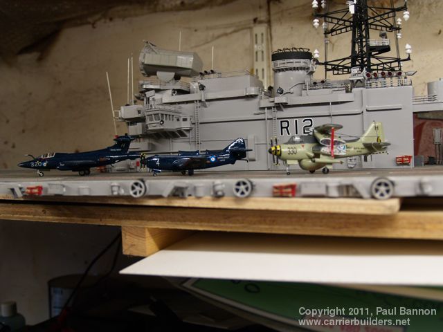
Having built the basic Island I now began it’s completion. As with the Truman the Island is fitted with a camera looking out through the Bridge windows. Not being very knowledgeable about these small cameras, I think I may have put it to far back from the windows - the frames being clear and the forward deck ever so slightly out of focus - something to remember if you are ever thinking of going down this road. The 984 Radar is powered but it took some arrangement of gearing to get it to turn slowly enough, the real thing weighed 28 Tons (Imperial) - and did not turn very fast. I used a motor and gearbox from an electric car mirror driving a 15mm cog with a pulley on it driving a belt to a small pulley under the radar - it finally rotated at a reasonably sedate pace. the deck under the radar was made removable incase of problems with the drive, as there inevitably was. After various adjustments to pulley and belt everything settled down and works every time it is switched on. The only other working parts were the navigation lights and the deck flood lights. Nav lights are grain of rice bulbs and the flood lights super bright LED’s. When switched on at night the LED’s effectively light up the flight deck surface. The lights were built in as the various decks were completed. The lattice mast was made as a separate item and the wiring for the mast lights was fitted in the box conduit that cared ALL associated wiring on the original. The mast was the last item to be fitted being rather fragile. Two things I am not very good at are soldering and spray painting. A result of this is that the mast is made entirely from Styrene and took almost three hours to paint! Another thing that does not particularly fit under any separate heading is the smoke unit. Being conventionally powered it seamed reasonable to have smoke coming out of the funnel. The unit sits under the Island with a small raised outlet that exhausts into the funnel. The unit consists of a small tank for the smoke fluid, a wick made from Fiberglas rope which has a heater element wire wrapped around it. The wire came from a hair dryer element and how much is a mater of experimentation - to long , no smoke - to short, a fire ! Also fitted into the top of the tank is a 15mm computer fan, this doubles the amount of smoke created. The whole unit is driven from the speed controller on one motor which moves a servo to close a micro switch and bring in the fan and element. Adjusting the micro switch allows the point at which she makes smoke can be controlled. Part 4 to this article will be the Air Group but as this is still under construction, (only three so far) may take a while to appear. Although only 30 aircraft I have only been able to source ten aircraft as kits - the remainder will have to be made.
Photos and text © 2011 by Paul Bannon February 4, 2011 |