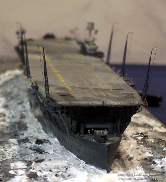
| When wishing to build a model of HMS
FURIOUS in her post 1925 rebuild to WW2 configuration in 1/700 one is faced with
three choices:
1) Purchase the Loose Cannon Models 1918 variant, keep the
hull and junk everything else and add your own to superstructure (this is a
viable option for a 1920's and 30's guise model ; the gun turrets are right and
quarter-deck at correct level)
2) Purchase the HP Models kit and engage in resin butchery and
build it to the best of your ability....
3) Purchase a set of plans from the National Maritime Museum
in London and scratchbuild the entire thing!!
This is the tale of option 2....
Upon opening the box I was initially thrilled with the
contents-- a brief dry fit however soon showed all was not entirely well....
There were a number of gaps, chunky platforms and some plain inaccuracies none
of which were particularly troublesome to a moderately experienced modeller.
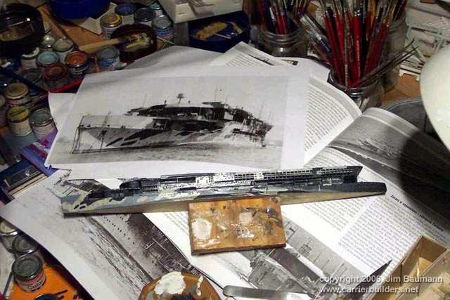
I have always visualized Furious in WW2 as being quite low and
sleek ... the above dry fit immediately struck me as being very tall and
lofty....checking photos and measuring with dividers, seeking opinion on message
boards, guessing and wondering soon had me in a quandary. I was fortunate to
have been loaned a set of NMM plans --this established after a session armed
with paper and calculator that the assembled kit would be between 2.2 and 2.3mm
to tall, this in itself is not a vast measurement, in a 1/700 carrier it upset
the visual balance of the model!
I was determined to have a WW2 Furious!... so here is how I
went about it!
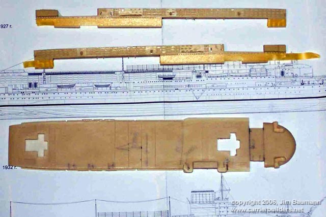
First of all I established that the lower hull casting was
dimensionally fundamentally OK, the main problems lay with the deck thickness
and the hangar side heights and proportions of the 'cutouts'.
|
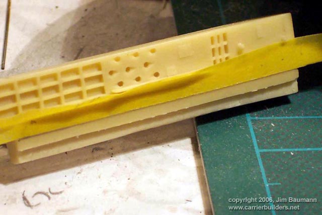
| I used dividers, pencil and Tamiya Masking tape to mark off
where the material was to be removed. |
 |
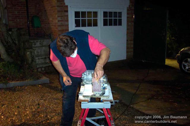
| This was achieved using my trusty belt
sander (as ever, used at night!) |
 |
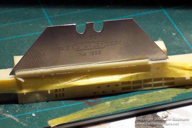
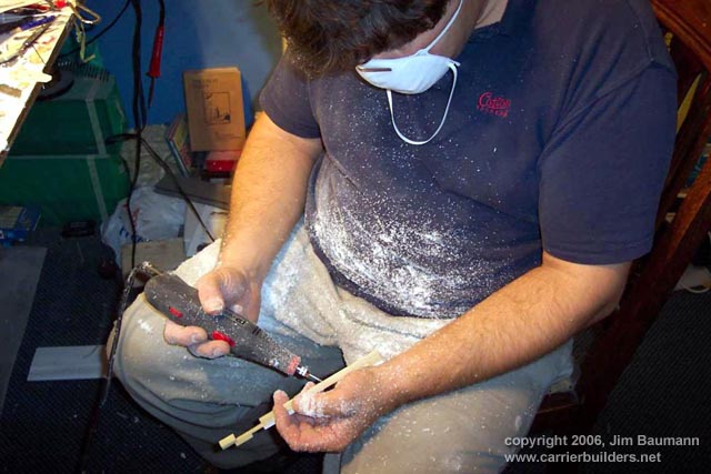
Other recesses were achieved with saw cuts and the use of a Stanley blade as a
chisel along with some hefty blows of a hammer. This gave a very crisp straight
cut edge to the resin, proportions of cutout heights and steps being adjusted
with styrene strip.
|
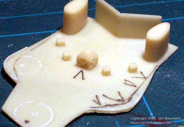
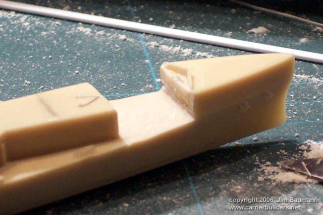
Another manufacturing shortcut in the hull casting I wanted to cure was the
forward deck undercut. On the real ship this was the capstan deck and the
overhead deck was held up by struts with gusset plating for rigidity. On the kit
hull it was relief rendered only... this called for sawing, grinding and some
delicate work with brass and styrene.
|
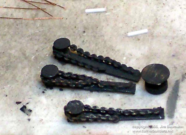
| I made some capstans from Model railroad
brass bits , styrene chainways and brass chain.
In amongst this surgery the commendably thin resin bulwarks
had collapsed and were replaced with styrene items, this time angled correctly
to the outward slope of the superstructure.
Further fwd I made them of paper. |

 |
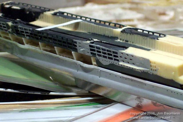
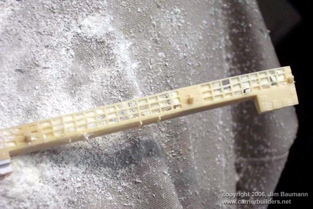
| Close scrutiny of the NMM plans (bearing in mind the numerous
refits and changes to the ship since the plans were drawn) showed the flightdeck
to be too short. I lengthened the casting at the appropriate point using styrene
shims . I also sanded the deck extensively in thickness as well as plan profile
to give the distinctive humpback shape. |
 |
|
|
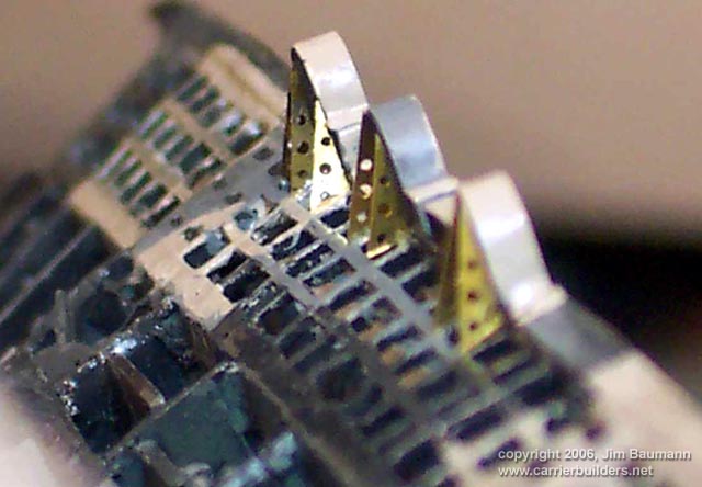
| In the above operation I intentionally
removed the AA tubs (too clunky, wrong shape and wrong place) and
un-intentionally the neat representation of the holes all along the flight deck
edge Close examination of photos showed these to even more frequent than the
removed items. I did not however relish drilling all those holes perfectly... so
I cheated! Using some GMM canvas dodger railing PE cut in half with scissors did
the trick nicely. I cut and joined the strips underneath the guntubs so as to
prevent later buckling with expansion and contraction problems caused by
temperature variations. |
 |
|
|
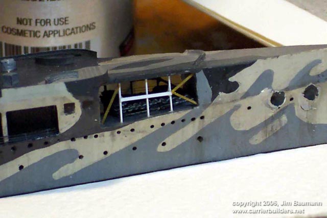
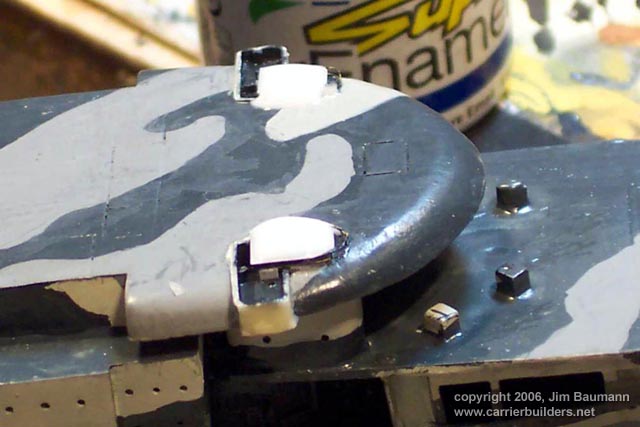
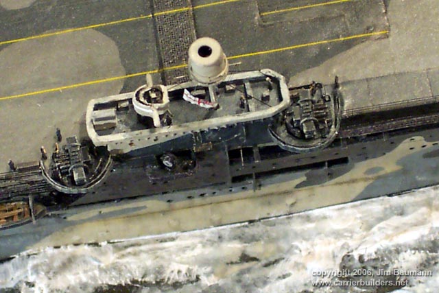
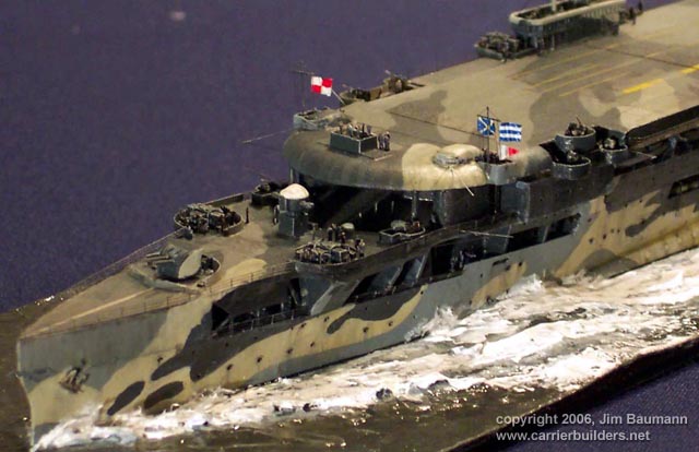
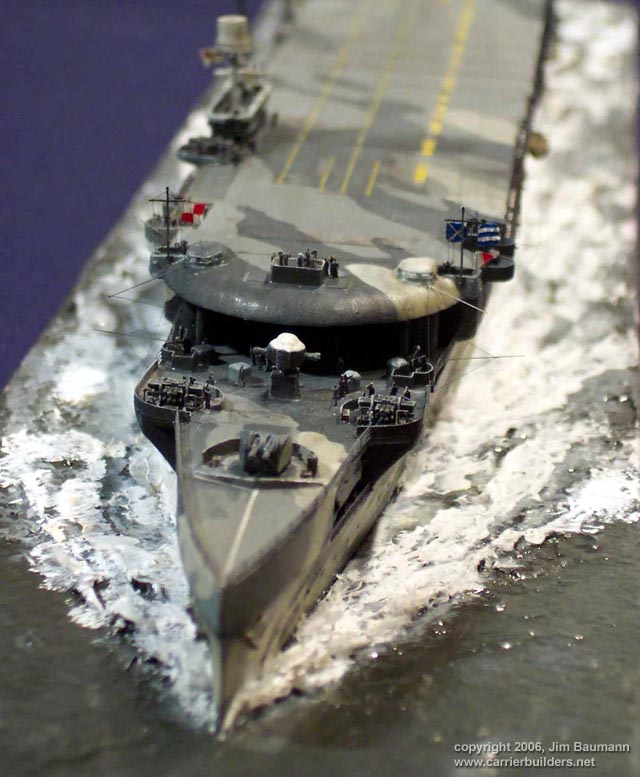
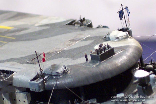
| HMS Furious was initially rebuilt without any kind of Island
structure, conning of the ship being carried out from two 'pods' port and stb of
the forward edge of the flightdeck as well a retractable navigation 'bridge' in
the forward center position of the flightdeck . The latter was built from
styrene and stainless steel PE scrap. The port and starboard conning tops were
given a domed roof of white glue and windscreens of PE handrail. |
 |
|
|
The funnel and exhaust arrangements of the
ship were unique. I wanted to represent the funnel tubes behind their cooling
'egg boxing'. In the kit it was anticipated that this recessed space would be
painted black--photos of HMS Furious show the exhaust trunking to be visible
behind the egg boxing. . This I feel really should have been a PE piece-- it
would have rendered that area so simple and crisp! --alas I arduously and very
carefully ground out all the resin behind the 'egg boxing', until such time only
thin wafers were left between the uprights and horizontals; these were pushed
out and the grating cleaned up with knife blades. I installed the tubes as a
representation of the exhaust funnel trunking.
|
 |
|
|
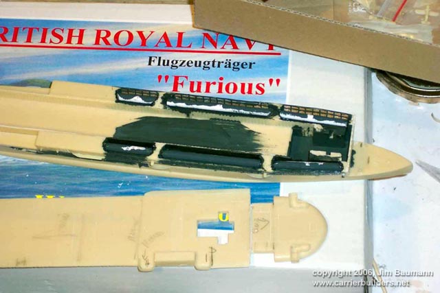
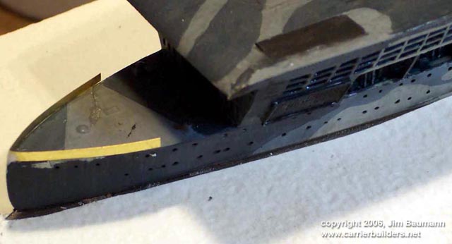
She possessed large exhaust vents on either side of the aft flightdeck; these of
course impeded any kind of landing on.... So the smoke was exhausted out of the
aft lower quarters of the ship when flying operations took place, the changeover
being made via flaps in the ducting . This operation was referred to as 'smoking
up / smoking down! An unwanted side effect of 'smoking down' was that exhausted
sooty deposits soon made the aft end of the ship unsightly- the counter-measure
was to simply paint the aft section of the ship black!
The lower exhaust ports were made of scrap PE and styrene
strip. |
 |
|
|
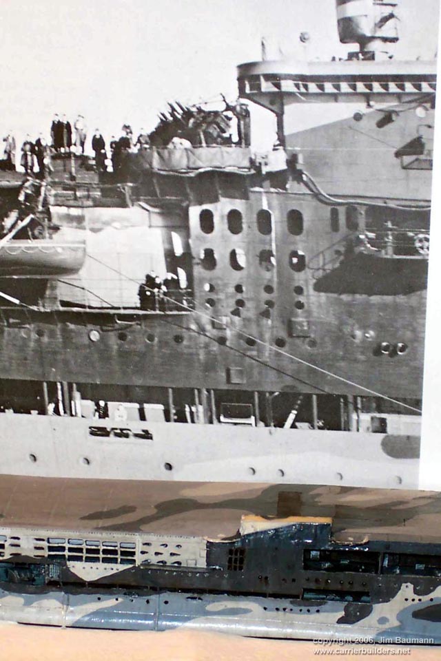
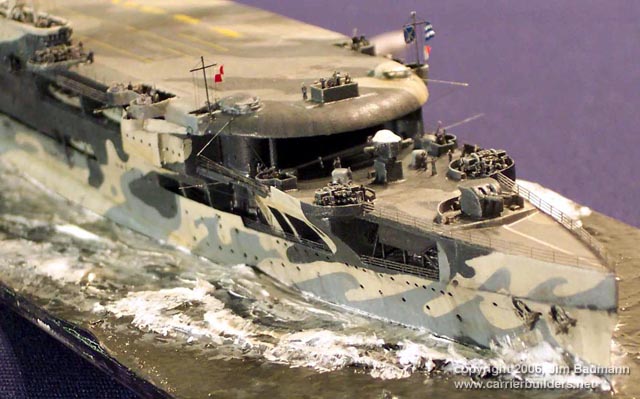
| The Port side of the camouflage in this
scheme is very poorly documented- after an appeal on the
message board I was soon sent this excellent photo! Thanks Miles! |
 |
|
|
| Having removed all AA gun-tubs new items were
fashioned from brass PE scrap, a crisper medium than styrene strip. |
 |
 |
|
|
| The braces fitted to the undersides were
cut down from the WEM Ark Royal radio mast PE parts This fret was used
extensively for all the wrong applications! |
 |
|
|
| Further work carried out on the hull sides involved replacing
most boat platforms and fitting these with braces, cut from 1:200 ladderstock,
as well as fitting the flightdeck drains made of styrene strip. |
 |
|
|
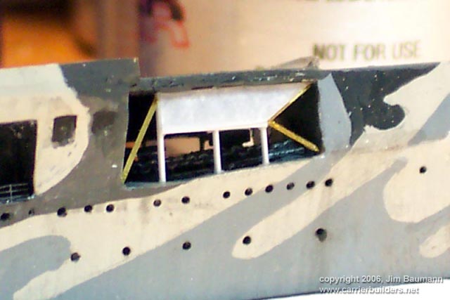
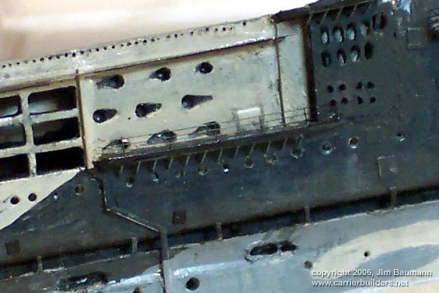
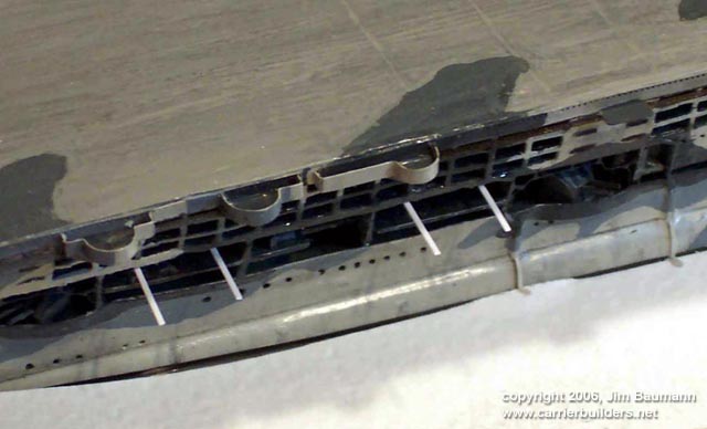
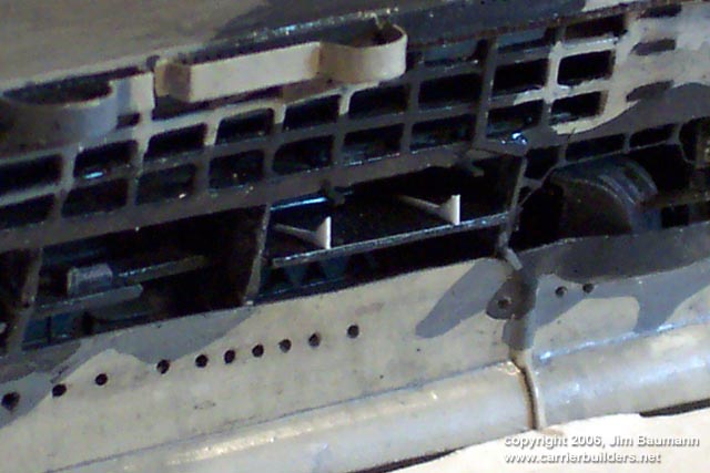
| Infuriatingly I noticed at a late stage of
construction that the apertures in the panel below the Island were hopelessly
incorrect in appearance, as well as not being pierced through tom the hollow
behind. |
 |
|
|
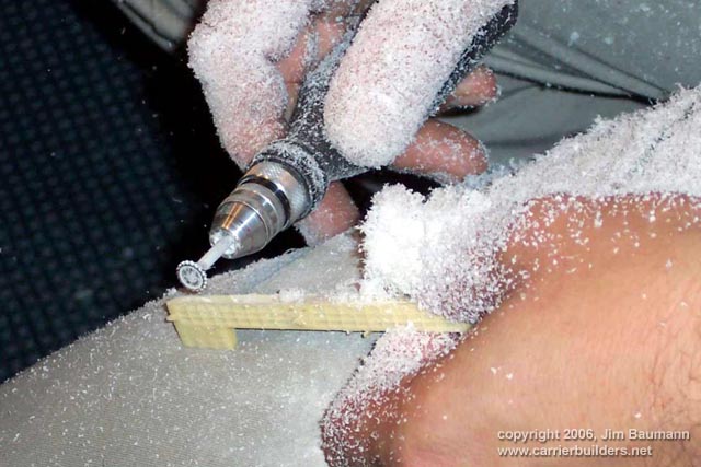
| I had to cure this fairly minor feature, the grinder quickly
made a recess leaving an uneven surface. This was lined with a piece of brass. |
 |
|
|
| I made the new aperture panel from thin
styrene, cut and drilled the holes , in my view a vast improvement... the
process was repeated on the port side. |
 |
|
|
| The 4" HA/LA mounts were the kit items correctly supplied
with the larger shield, these were fitted with the fire arc limiting rails,
these can just be discerned in some photos of the real ship, a feature rarely
modelled in small scales. |
 |
|
|
| The Flight deck surrounding catwalk
'floors' can look heavy in 1/700 , I used GMM Goldplus destroyer netting; whilst
this is not exactly correct it does succeed in giving a very lightweight and
airy final appearance when fitted with the handrails separately. |
 |
|
|
| The davits for the shipsboats in the 'hollows' were made of
two different sizes of styrene strip after the boats were in place, |
 |
|
|
| The boat cradles were made one-sided of
paper, glued in place with CA and the boat was slid in sideways. |
 |
|
|
| Unfortunately not a single kit supplied boat
could be used as they were all generic rowboats. These were all replaced with
WEM Pro items.
I partially recorded the sequence of placing the ship in her
sea. All my 1/700 models reside in wall cases.
which all have timber framed shelves of uniform width -this
allows interchangability of models within all cases |
 |
 |
|
|
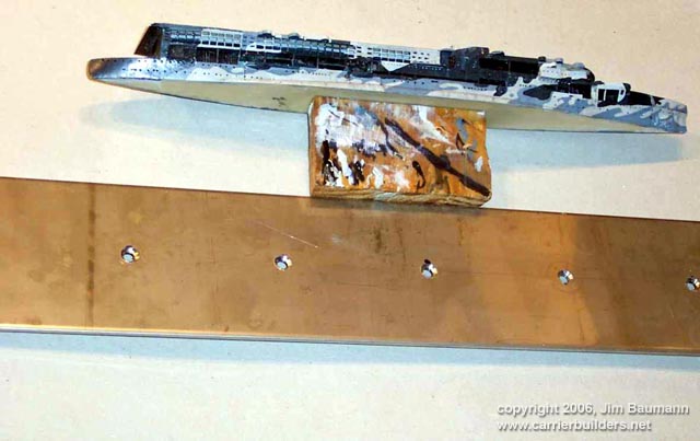
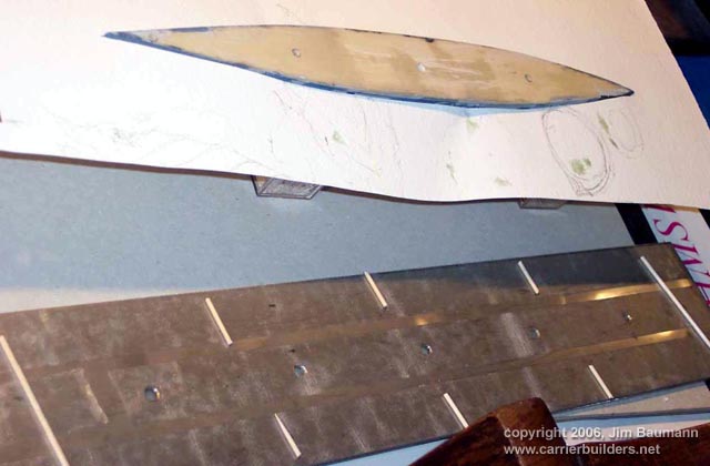
| The ship was supported on padded supports
on her flightdeck upside down. The 3 mm stainless steel plate had been pre
drilled with countersunk holes so as to allow the resin hull to be screwed down
to eliminate any later warping or hogging. The wave pattern had been created
using cocktail sticks, the embossed artists watercolor paper earlier had the
hull shape cut out fractionally larger than the waterline footprint. This was
affixed to the plate using double sided tape giving an instant fix. I first
separated the well used timber 'build handle' and placed the model onto its base
having first pulled the 'water paper' up around the models 'waist'. |
 |
|
|
| The model was then screwed down using the pre drilled and
tapped holes using stainless steel screws. Unfortunately one of the holes was to
close to the stern, possibly the hole had not been drilled deep enough ; while
giving the screw its 'final' half turn the stern neatly cracked off!!! |
 |
| I neatly re-glued the stern(!) repainted
the area and vowed next time to have more holes in the plate to give more choice
in screw placement! The watercolor paper was then soaked in CA to make it
moisture proof and hard. |
 |
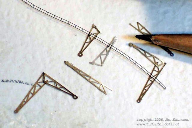
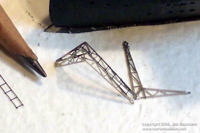
| While at the stern I elected to make the cranes
at the aft hangar entrance. These are unusual in being square in shape so as to
allow their stow position under the flightdeck, the kit items being solid resin
and hence of no use I manufactured two cranes cobbled together from GMM Carrier
PE and handrail |
 |
 |
|
|
| The model was painted using WEM and Humbrol
enamel paints weathered with watercolor. The sea color chosen was a dark grey
mixed with just a hint of green, so as to portray the cold waters off the coast
of Norway. I extensively used toothpaste to back fill gaps and create
translucent wave crests made with a flat spade brush to complement the spindrift
and spray made of torn tissue paper. |
 |
|
|
| The pompoms used were WEM resin items dressed up
with PE as the kit items were way too large. The cast anchors were removed and
replaced with WEM PE items. The large homing beacon was made of aluminum tube on
a disc of PE furnished with handrails. from GMM Goldplus as were all the
remainder of rails fitted to the ship. |
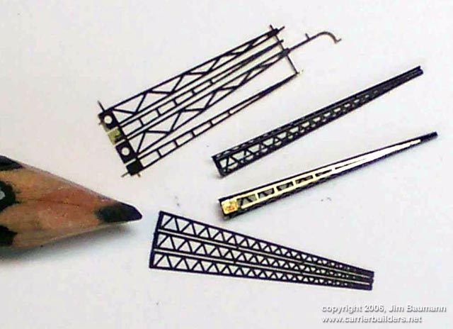
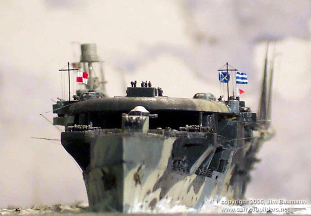
| The large radio aerial masts were made
using a combination of GMM and WEM items topped with wire 'hockeystick ends' .
The GMM PE masts were 3 sided only, the 'open box' was supplied with a lid from
the WEM set. These were rigged with stretched sprue. The radio aerials are
portrayed in an upright position as no flying operations are taking place. Most
photos of Furious underway show an empty deck, RN carriers of that era had no
aircraft deck park. This fact contributed to the loss of her half sister HMS
Glorious, but that is another story and another model! |
 |
|
Click on the images to enlarge!
|
|
HP models must be commended for having made an excellent
choice of a great and esoteric subject that fills a gap in any RN carrier
collection. Unfortunately the elation was marred by the kit being disappointing
considering its high price- many things could have been so very much better,
accurate and more satisfactory with only a little more effort. The use of PE for
some of the structure would have made the result so much crisper in final
appearance
My thanks have to go out to all my 'virtual' message board
model friends around the world who rallied to my aid with photos, help, drawings
and plans main References used :
-
NMM Greenwich plans
-
Warship profile 24
-
R A BURT British battleships 1919-1939.
-
British Aircraft carriers Norman Friedman
-
Alte Flugzeuf traeger Marine Arsenal (Breyer)
|